This website is a cache of a forum thread on smartcar451.com that outlines my conversion of a 1993 Honda Del Sol to electric power! If your on dialup, you should'nt be! All the content is in one place down below. As time permits a REAL website should be made. If you wish all the pictures and more can be listed in a gallery here:Honda Del Sol EV conversion
Posted: Sun May 22nd, 2011 05:28 am
I have thought about it for a couple months now. The smart car fits my "around town" lifestyle pretty well. With the exception being my month long trip across the country.
I say this because I am convinced an electric smart car can be made much cheaper then the upcoming smart ED. Along with that, I also think the parts are out there to make it a superior vehicle.
I mention this because I am seriously considering going to a workshop designed around converting cars to electric.
I have followed the EVTV website for a while now and they are top notch group of people. Everything is documented in video form to explain and discuss the problems that do arise.
When I heard they where going to have a workshop with a limited number of people and vendors in attendence I thought "What a interesting way to spend 4 days!".
I would go there to gain knowledge to perhaps one day convert my own smart car to electric. The website already has a smart car they plan to convert to electric but the last I heard they are waiting on China to hopefully utilize hub motors to power the vehicle.
The main website is at: http://www.evtv.me
And the event is at: http://www.projectooc.com/evtv/evccon_itinerary.php
I will report back my decision.
5/28/14: To recap this thread. I ended up converting a 1993 Honda Del Sol to electric power. In this thread you will find my progression through the process. This project will continue to evolve as I find things to make "better".
The car is driven daily and is alot of fun! I gallery of just some of the pictures is located @ http://www.techvelocity.com/delsolgrouped/
Posted: Fri Jun 24th, 2011 02:38 pm
OK, I am officially doing this! I just registered today and am pretty excited about the possibilities.
Posted: Thu Aug 4th, 2011 03:32 am
They have an excellent show up this week involving battery testing! Check it out if you have a spare hour OR TWO!
Posted: Tue Aug 16th, 2011 03:38 pm
Wow!,
I have'nt even attended this event yet but the amount of information I have found on the internet is amazing. The more I see what makes a good electric car, the more I am actually pushed away from using the smart car as my first canadite. The required specs for a good EV are the following: Lightweight, space for batteries, manual transmission. With that in mind I cannot find one that meets all the specifics. My idea is either a Cadillac Catera or a Lincoln LS. The Caterra was never offered with a manual transmision (but it was overseas as an Opel Omega) but the Lincoln LS was in 2000-2001 but is heavy @ 3700-3800lbs. So its a matter of personal preferrence as to what car I chose. Having owned nothing but GM for many many years I am all to familiar with the types of cars they produce. So having said that, the best case scenario would be to reduce weight rather then convert an automatic car to stickshift. So my choice at this point is an 00-01 Lincoln LS V6 stickshift. I am not even sure at this point I can build a superior car to an OEM for the price. The biggest cost involved is still going to be the batteries. This is going to be fun!
Posted: Sat Aug 20th, 2011 07:49 am
I am probably just "spinning my wheels" until I actually attend the event, but..... I have been looking online and to get the 200-220ah 3.2v cells in enough quantity to have a 75 mile range I am looking at $11000.00! At the rate things are moving in the EV world I think it would be foolish to drop that kind of cash on something that will surely be bested not 3 months later. So my plan at this point is to build up a car with a min spec battery pack. Everything else will be overbuilt, good motor, good controller, good charger, etc. Then a year down that road replace the batteries with a larger and better pack.
Posted: Fri Sep 30th, 2011 03:06 am
Back
from the event! What a fantastic time. A lot of the information I was
already familiar with. But if I did have a question, a representative
from the company was there to answer them.
I am confident this event will go down as a turning point for
electric vehicles.
I
am coming at this full speed. Many of the contacts I made at the event
are ALREADY sending components for the build. This before I even have a
car!
I may comment further on the event but having driven from my overnight stay in Oklahoma to Ca straight through, sleep is in order.
Posted: Thu Oct 6th, 2011 12:02 pm
Things are falling into place.
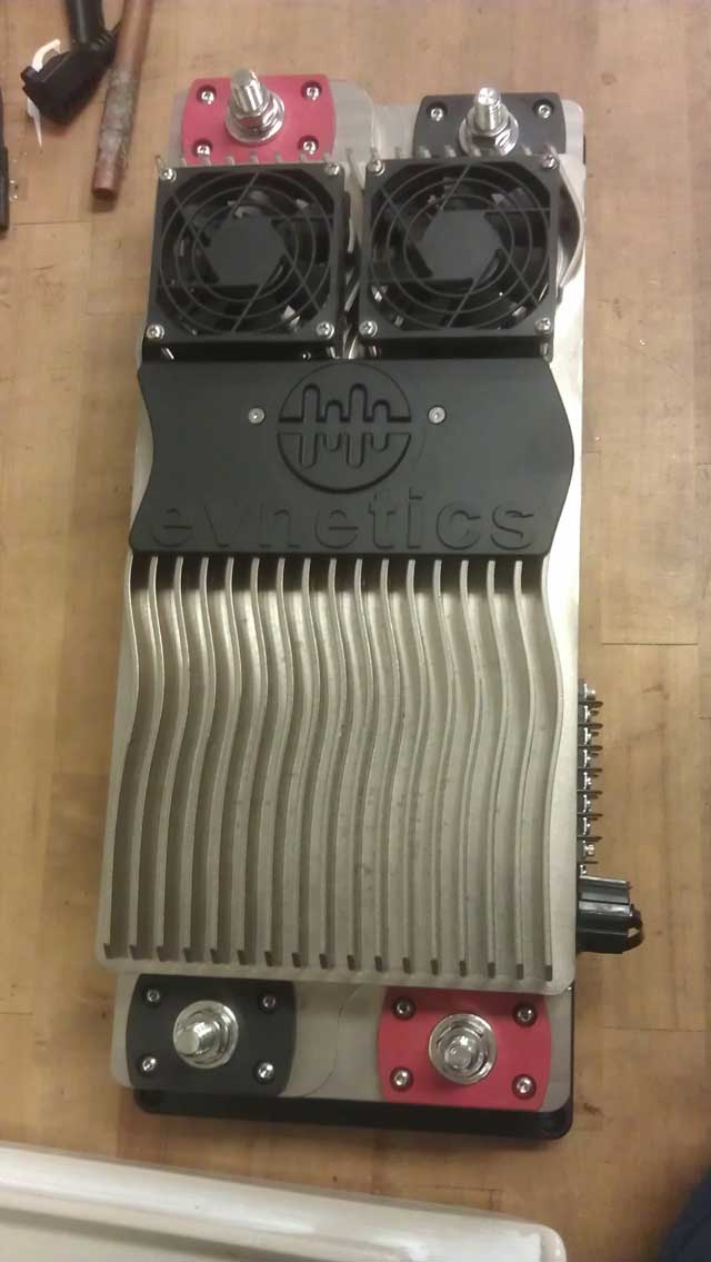
When
it comes to EV's the motor controller is the "brains" of the car. Think
of it as a regular gasoline engines ECU/PCM. When it came to make a
decision on the brand I can already tell you I was a little biased
towards the evnetics unit. And as a sponsor of the EVTV show I watch I
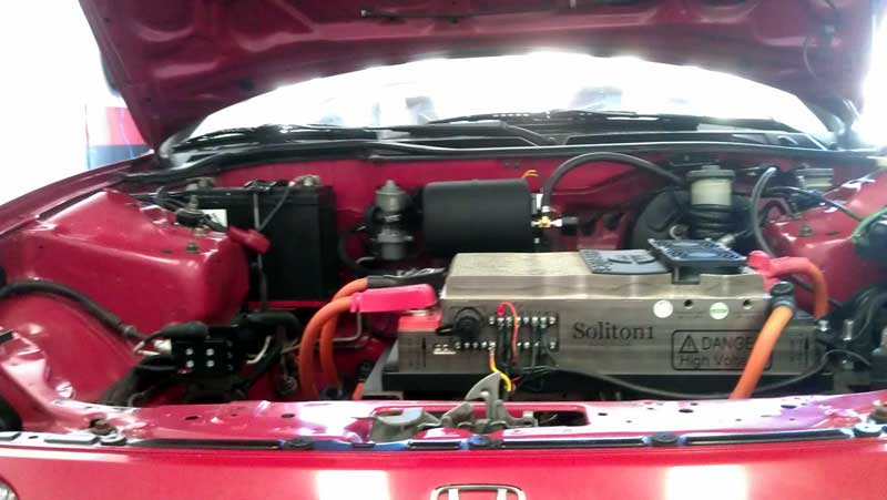
feel the need to support them. I have read extensively on the Soliton1
controller. Everyone I have talked to loves the unit. It is HIGHLY
configureable and the support evnetics offers is top notch, both online
and on the phone. I was fortunate enough to meet Sebastien Bourgeois
from evnetics at the EVCON event a couple weeks back. What a stand up
guy! He answered all my questions (even dumb ones) with ease.
Because
of this and even before I have a car picked out, I have purchased a
Soliton1 controller for my build. It's TOTALLY overkill for my project
but I figure it is better to understress then overstress the components.
Read all about it here: http://www.evnetics.com/index.php/soliton_specs
Posted: Sat Oct 8th, 2011 02:51 pm
I have been busy and until I get the time to get some of my
own photos of EVCON up, check these out!
http://gas2.org/2011/09/27/electric-vehicle-conversion-convention-mega-gallery/
Posted: Fri Oct 14th, 2011 03:01 pm
The controller came yesterday. I am going through the instruction booklet now which is quite nice! Still need a car!
Posted: Thu Oct 20th, 2011 09:17 am
After
removing the controller from the box I noticed what I thought to be a
plastic retaining nut on the ethernet port to be cracked and missing. I
contacted EVnetics and was surprised to learn this was the actual port
that was broken in shipping thus requiring the controller to be
returned to FL. I guess it was better to find this out now. EVnetics
has been GREAT about this issue and am awaiting a call tag for pickup.
On the car hunt front things are looking up. I am seeing a car tomorrow afternoon. If that does'nt pan out I am either going to TX or FL for the purchase.
Posted: Thu Oct 27th, 2011 03:24 pm
OK here is a breakdown of cars I have been seriously
considering.
01 Lincoln LS stickshift (somewhat rare but obtainable)
1993 Honda Del Sol base model stickshift
1999 Mazda Miata
All have pro's and cons.
The
Lincoln is heavy. The Del Sol, everyone modifys and its not usually
tastfully. The Miata is looking like the best scenario so far.
I have looked at 8 Del Sol's and not a single one I would consider purchasing!
Posted: Thu Nov 3rd, 2011 01:29 pm
The controller is due back tomorrow. They replaced the broken
(in shipment) ethernet port and its as good as new.
I am still looking for the right vehicle. Its the most trouble I have ever had finding a car!
Posted: Sat Nov 5th, 2011 02:36 pm
Happy days!
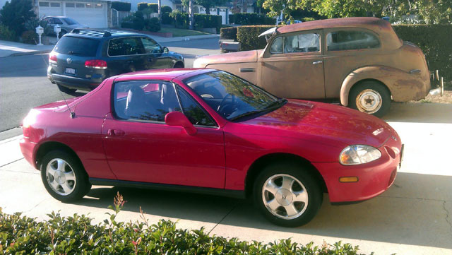
Just when I was getting fed up, I found a car!
Earlier
in the day I had seen a 95 Miata that was in OK but not perfect
condition. I made an offer and the guy did'nt even counter it and left.
Then
when I got back home I looked on my cell phone on craigslist for more
Miatas. Nothing I had'nt already seen. So I decided to look for Del
Sol's again to see what was out there. I saw a nice 1993 Del Sol with
72k miles in great condition minus a couple little dents and a tear in
the driver seat bolster. I had totally missed this ad because I had
been looking for Miata's. The ad was 5 days old and I was happy to hear
that the owner still had it! I hot footed it up to Torrance about 50
miles away and looked it over. I made an offer and the guy quickly
accepted (which leads me to believe I should have offered lower) but at
this point in the game I was over haggling and just happy to find a car
that fit the bill.
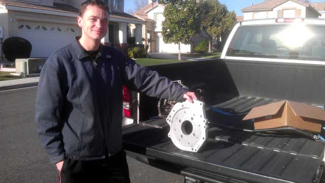
This picture was taken
with a cell phone camera and thus the red's appear pinkish. I assure
you however the Del Sol is fire engine red. Going to take a couple days
to drive it around to ensure its mechanical intergrity before I rip it
all apart. It also needs a good detail which I will do.
The Del Sol does have a driver airbag and power steering but no ABS (which I dont want). I found a resource online that instructed on how to convert a Miata power steering rack to manual. It involves capping of the hose lines and removing 2 internal seals so the rack movement will not cause internal pressure. I don't know it this applies to the Del Sol steering rack but I will check. There was also a manual rack available that year if all else fails.
Posted: Sun Nov 6th, 2011 01:52 pm
As
is customary, I spent about 5 hours today stripping the old wax off and
polishing the Del Sol. Tomorrow I will finish it up with a coat of wax.
It looks good!
I am really satisified with
the purchase. Yesterday I also jumped the gun and put the stock Honda
engine on craigslist. I found the engine model code (D16Z6) and did a
search. I found a wanted ad that was placed 3 weeks ago and hope that
comes though. I wanted to get a buyer now while its in the car before I
pull it. The engine is a VTEC model, although the 125HP version. The
car gets smogged tomorrow and then Tuesday comes the charger install in
the garage.
I also unpackaged the controller and everything looks great.
Posted: Wed Nov 9th, 2011 02:28 pm
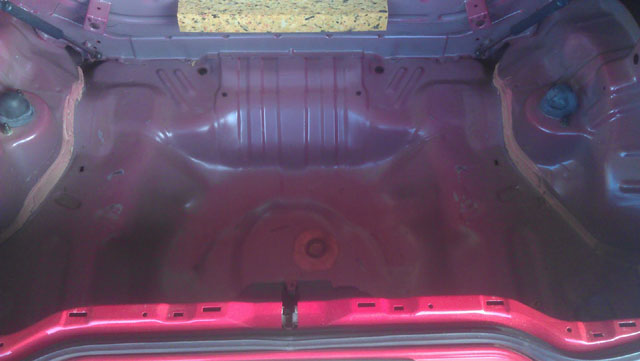
Did alot of measuring and eyeballing. The car got registered and the trunk got all the carpet removed. I am seeing a surprising amount of space. The plan is to keep the roof storage rack installed and mount the batterys below that. I also noticed the back wall of the trunk has 4 threaded bolt holes. This will be usefull to secure items.
Posted: Thu Nov 10th, 2011 12:14 pm
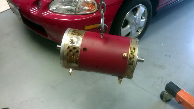
oday
I went to "EV west" and picked up a Netgain Warp9 motor and also a
Level 2 J1772 charging inlet and hardware to adapt it for use on the
Brammo. That's really a side project at this point. If I don't like it
on the Brammo I will use it for the Del Dol, I planned on buying one
anyhow.
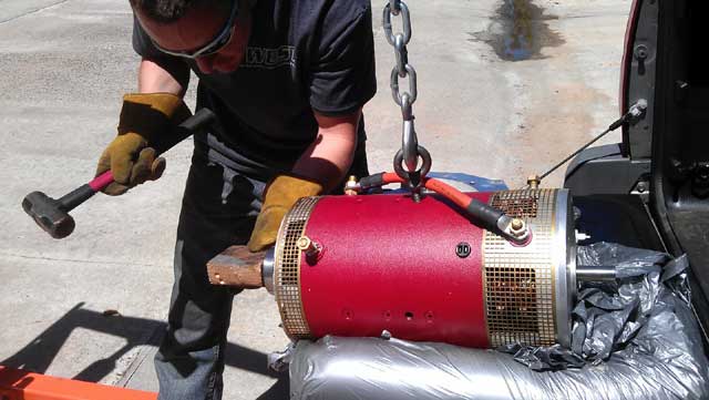
@ EVCON a presentation was done and
we where all told that only after about 60hrs of continuous running
does the motor brushes break in. This is an often overlooked procedure
but is cruicial to brush life and motor performance. So I set off to
break the motor in on a test bench with a battery charger @ about
12amps. Sadly my charger could not continue supplying this voltage
without shutting of and resetting once cool. I switched the charger to
it's 2amp setting and the same happened. I guess at this point I will
look for a 12v 10-30amp regulated power supply for this task.
The
guys at EV west where VERY informative and had a lot of great ideas.
Both of the guys where a little tongue in cheek when they said a little
Del Sol with a 160v battery pack and a Warp9 motor powered by a
Soliton1 controller should be a fun little car. I concur.
http://www.evwest.com/
Posted: Fri Nov 11th, 2011 02:07 pm
Today
I went and got a new 12v 2/10/50amp charger. I ended up getting the
automatic model because I will use this for batterys once the motor is
broken in. However because of this feature I am finding it difficult to
get a clean supply of 10amps. It is not sensing a battery to charge so
it wont turn on and supply voltage. I even hooked up a motorcycle
battery to "turn on the charger and limit the power output to the motor
the same that is being supplied by the charger. Long story short that
did'nt work.
And in true geek mode I grabbed a spare 450watt computer power supply, jumpered the green wire and the black wire via a jumper cable on the ATX cable to get it to turn on. I hooked up the connector that supplys 12v. Again it did work but I started to sense the wires getting hot and decided not to start a fire and I turned it off. So again I am looking for a solution. At this point I think a regulated power supply would be a wise investment.
Posted: Sat Nov 12th, 2011 07:38 am
I
went to the local Fry's to source a 12v power supply. I saw a 10amp for
$40.00 but looked cheap. The 20amp model looked solid but was $100.00.
I know this power supply will sit dormant for a LONG time before I used
it again I didn't see the need to spend that kind of money.
As
I left Fry's I did a Craigslist search and found someone 2 miles away
from the store (which was already 15 miles away from home). I swung by
and picked up the 8 amp power supply for $20.00. I figured 8 amp would
be enough because even the battery charger on its 2amp setting would
spin the motor, just not very fast.
I got home and hooked it up an turned the power switch on and NOTHING. I verfied the power supply was putting out electricity, but not enough. So I hooked up the battery charger I had @ 2amp and turned it on. The motor immediatly came to life and I switch off the charger. The power supply just needed a litle boost to get the motor turning. It is now 2 hours into its quest for a 60 hour brush break-in.
Posted: Sat Nov 12th, 2011 10:53 am
OK, correction. As it turns out the power supply slowly ramps up to its rated output in 30second increments. Everything works as it should now, no "jump start" required. I also added a fan to cool the power supply. The motor itself is staying VERY cool.
Posted: Mon Nov 14th, 2011 03:05 pm
Today
I rearranged the garage preparing for the Del Sol teardown. I would
like to finish breaking in the electric motor before I decide to remove
the factory engine. Mostly because I am using the engine hoist to hold
the electric motor. Once that is complete I will lower the electric
motor back down into its shipping box and start with the gas engine
removal. I am currently at 30hours of the 60 recommended to seat the
motor brushes. I am not running the motor unattended. I have faith in
the electric motor however the power supply I am less trusting of.
Because of this I am usually doing 3-4hour run sessions between me
daily activitys.
Always wanting to have 2 irons in the fire I set off to add a J1772 charging port to the Brammo. The only space I could find to centrally locate the port was up above the power button on the "gas tank".
Posted: Fri Nov 18th, 2011 03:21 pm
So no sooner then I got the smart car back from repair did I spend a good 4 hours disconnecting items and draining fluids in the Del Sol. Everything is ready to lift the motor out tomorrow.
Posted: Sat Nov 19th, 2011 08:08 am
I
was generally unmotivated today and spent time doing other things. But
I did remove the full exhaust with muffler and the gas tank including
the hard lines. I can now turn the hot water heater back on with no
fear of blowing the house up.
I did'nt pull the engine even though it looks ready. I am becoming more convinced that leaving the transmission in the car while removing the engine IS possible however it wont be a clean removal and will likely scrap the engine bay up. So at this point I am going to remove them both as 1 unit. The only question now is to drop it out or pull it out.
Posted: Sat Nov 19th, 2011 12:04 pm
Again, I have changed the topic title to be a more accurate
description of the direction its going.
It also appears the GE wattstation charger was the right choice. Both REC solar (major player in solar) and CODA automotive have signed agreements to sell and distrubute the wattstation.
Posted: Sun Nov 20th, 2011 02:44 pm
The engine and transmission are out. Everything went smooth and I ended up lowering the two while still connected to the floor. Next thing that needs to happen is seperate the transmission from the engine and get that back in the car because Tuesday is going to come very quickly. I removed the entire front suspension. And in doing this I noticed one of the original struts was starting to leak oil. Depending on how tomorrow goes I may delay EVWEST coming up until a new suspension setup I have been eyeing is sourced.
Posted: Mon Nov 21st, 2011 04:09 pm
The engine/transmission is split apart and on the ground. I ended up gettting OEM Gabriel style struts as replacements. From everything I have been reading about TEIN and Skunk coilovers leaves me to wonder about the long term durability. If I do end up needing a ride height adjustment due to weight placement I can always getting a higher springrate of the OEM springs. EVwest will be here at 8am to do some measuring for a motor adaptor.
Posted: Tue Nov 22nd, 2011 03:33 pm
The boys and girls from EVwest (the girls where absent) came up from San Diego!
They did alot of measuring and decided it would be best to take the transmission and flywheel with them! So so much for putting the transmission/axels/suspension together while I wait for the plate to be made, really no big deal.
They took alot of time looking at the car and engine bay. They see alot of space to put batteries. And more then once it was mentioned that a warp9 motor and a soliton1 controller was going to be ALOT of fun to drive. While I was waiting on a right size socket to remove the flywheel to be delivered, both the guys took a ride on the Brammo. That was a good time killer as we killed 20 minutes talking about the bike.
IF there is room I have been thinking of running a plate on the back of the motor to drive the power steering,A/C and vacumn pump for the brakes. On the other hand if there is no room I may actually shorten the motor by shortening the armature shaft, that will be the last resort. I think I will be ok with packaging.
I am going to find little things to do on the car and research a good clutch/flywheel combo. So far a Stage3 SPEC clutch combo seems to be the way to go.
Posted: Mon Nov 28th, 2011 12:57 pm
I called EVWest today to check on the status of the adaptor plate. I was excited to learn that barring any problems they plan to have it done THIS week! I am busy searching around online for the best clutch to use in this setup. I am not worried about it being "streetable" as I plan on not shifting the car very often. The exception to this will be rapid off-the-line acceleration and freeway driving.
Posted: Tue Nov 29th, 2011 01:12 pm
The
clutch has been ordered. I went with a Stage5 SPEC clutch. It is rated
at 505ft lbs of torque. The Stage4 was rated at 300ft lbs and the price
difference was $40.00 to the Stage5. I seriously doubt I will ever push
past 200ft lbs but it is nice to know the failure point WONT be the
clutch.
I have visons of internal gears from
inside the transmission and axle halfshafts spewing alien like green
grease from the CV joints all over the bottom of the car as I apply the
very obtainable 300+ft lbs of torque. No thank you....
A reminder, the original Honda engine was 106ft lbs.
For fun I hooked up the 12v battery to see what things might not work that I have to rewire. Not surprising everything worked except the aux fog lamps and even that might have to do with the relays not being grounded and dangling underhood. The HVAC system commands a valve to open up and let the coolant in the cabin to heat the car, and works normally.
Posted: Thu Dec 1st, 2011 12:40 pm
I called EVwest today to see how progress is being made. The plate itself is done being waterjet milled and they are waiting to source someone to make the keyway in the coupler. It looks like next week will be a more accurate timeframe. They told me if I could'nt wait they could find someone quickly to do the job, however I think they want to find someone to form a business relationship with for future customers. I said no problem and I will continue "geeking" out on the car dreaming up some overcomplicated solutions to simple problems in the name of being different.
Posted: Mon Dec 5th, 2011 02:19 pm
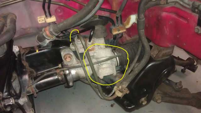
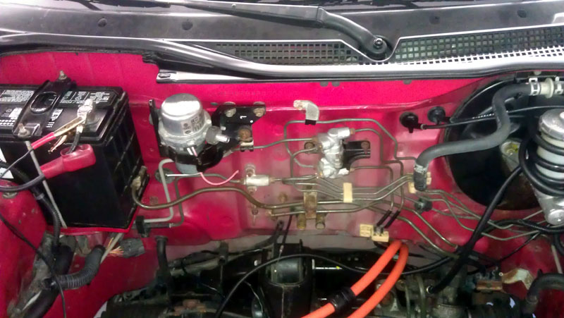
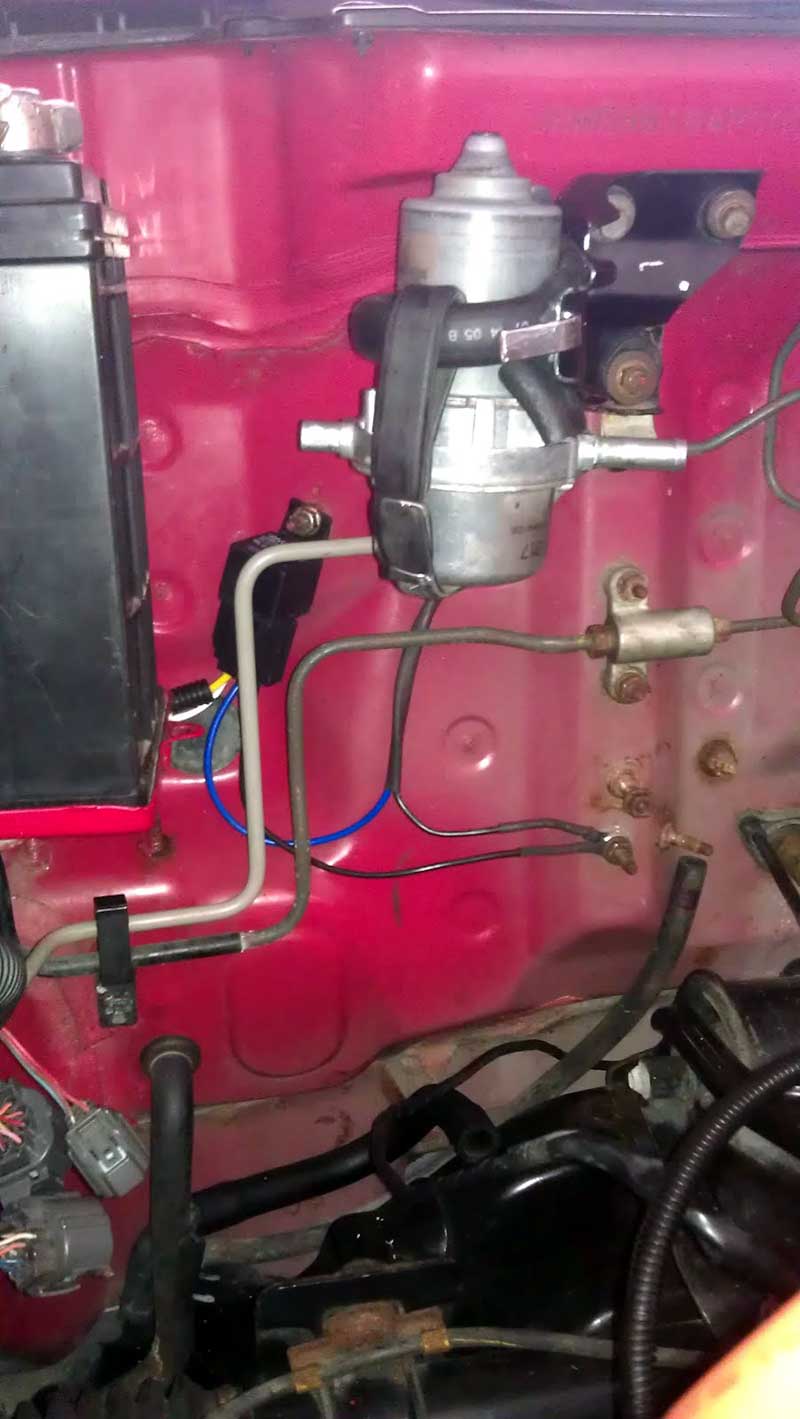
A couple of pictures of why I like this platform for conversion.
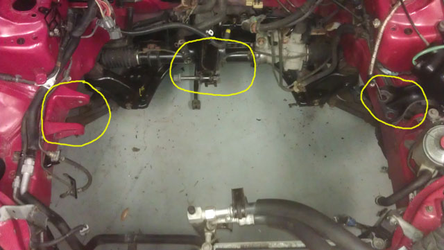
A mount on each fender as well as a mount on the subframe.
This is the HVAC controlled valve that lets coolant into the heater core in the cabin.
Posted: Wed Dec 7th, 2011 03:23 pm
I am expected to hear the status tomorrow on the adaptor plate
from EVwest.
I
was getting a little worried my SPEC clutch was M.I.A. I ordered the
clutch from LMperformance.com on the 28th of November and sent them an
e-mail on Friday requesting its status. The website only said the order
was sent to shipping and had'nt changed in 4 days. When I didn't hear
back I called again on Monday and left another message. On Tuesday I
got a voicemail saying the order had left on Monday and would be here
on Thursday, fair enough, I hope that is the reality!
I
am going to replace the front struts tomorrow since they are off the
car. It SEEMS plausible to go ahead and reinstall one side of the
suspension and axle.
As far as steering goes
I am going to take a gamble. A manual steering rack was an option for
this car and is readily available. When I was researching the
possibility of converting a Miata I found a website that gave
instructions on how to convert a power steering rack to manual. This
involved removing some internal seals so the pressure wouldn't build up
when turning the steering rack. It would make sense the instructions
would carry over to the Del Sol but I am unsure.
So basically I am going to try the same thing and I can always
fall back to installing a manual rack at a later date.
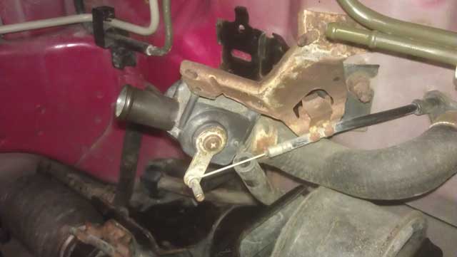
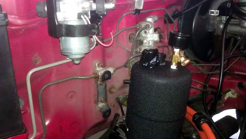
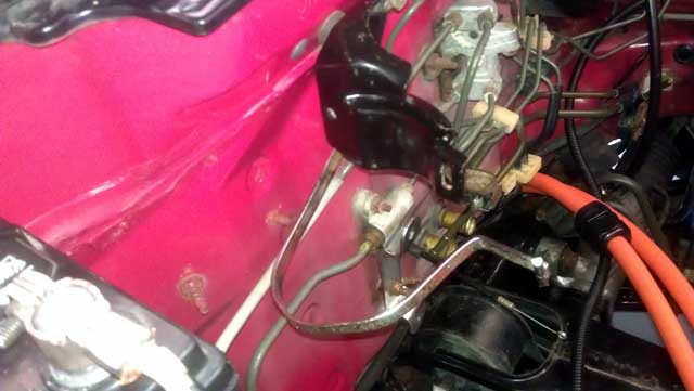
So
I am going to remove the internal seals (see right in picture). Then I
am going to fill the steering rack with as much mineral oil as I can to
act as a lubricant. The 2 steering lines (see left in picture) will not
be blocked off but rather will loop to one another with a small hose.
This is not a money saving tactic as much as it is trying to reuse as
many factory parts as possible.
Please excuse my MS Paint style highlighting.
Posted: Thu Dec 8th, 2011 12:36 pm
The
good news is the SPEC clutch arrived for the Del Sol as promised from
LMPerformance. I ended up going with the SPEC Stage5 setup. I don't
want the weakest link to be the clutch.
The
bad news is I called EVwest and they are now saying the adaptor is 2-3
weeks out! They are still having a hard time finding someone to machine
a slot in the steel adaptor couping.
So again I am going to find other things to do on the car, but honestly I am running out of things.
Posted: Sat Dec 10th, 2011 01:04 pm
I replaced both front struts today. I had them off the car and went to local shops to get a estimate on a simple strut replacement on the struts out of the car. I also had the new struts in hand. First shop said $140.00 and the send shop said $100.00. Not happy with this I ended up doing the job myself. Besides, all I have is time right now until the adaptor plate is ready!
Posted: Sat Dec 17th, 2011 05:16 pm
I
noticed news of Amazon.com now carrying the GE wattstation that I have.
This is great news and opens up another avenue for consumers to obtain
one.
Other then that I have been still
eyeballing the best way of hooking a radiator/heater. Today I noticed
the underhood valve is purposely not totally closed off when valve is
"shut" by the HVAC controls in the cabin. There is a hole in the valve
flapper. That would lead me to believe I could setup a Y connector
before the valve that would loop back to whatever I decide to use as a
radiator. I am not going to get to technical and close off the coolant
flow to the radiator when heat is requested in the cabin.
I
am taking off various brackets that will be reused and removing any
surface rust I see with a wire wheel and repainting them black.
The steering rack continues to leave me thinking. So again I have changed my plan. I am not going to remove the seals in the steering rack. I am going to "loop" the two hoses that go to the front of the car to act as a cooler.
Posted: Sun Dec 18th, 2011 09:34 am
I have often heard there will be a time in the conversion process when you will modify or remove something and realize there is no going back. I guess this happened today when I removed some hard metal lines from the fuel tank to the engine bay. I also took an air grinder and chopped up the stock exhaust/header/catalytic converter. The neighbors who are unaware of my project looked at me with a bewildered look.
Posted: Thu Dec 22nd, 2011 12:51 pm
Just
going back and forth via e-mail with EVWEST to get the rear tailshaft
motor mount made. I found a nice Google sketch up of a mount on https://sites.google.com/site/civicevkit/
I just have to pay EVWEST to input in Solidworks and then they can send to a local waterjet facility. They are closed down until the New Year however.
Posted: Mon Dec 26th, 2011 12:25 pm
I flushed the power steering lines with new fluid. I also put a small hose from the power steering cooler to the inlet of the steering rack. I found that a NPT fitting from a air compressor fit the thread pattern, and I had a spare handy. Its a temp solution until I can get the car on the ground with some weight on the wheels and go from there.
Posted: Wed Jan 4th, 2012 02:27 pm
I ended up talking to Matt at EVwest today. He sourced good Grade8 attachment hardware for the adapter plate. Still waiting on the machine shop to mill the coupler. He expects that to be done on Monday. So things are looking up that next week could be an eventful one. In preparation for that, I still have yet to put the new rear struts on!
Posted: Mon Jan 9th, 2012 01:31 pm
OK I am going to stop posting updates until I get the adapter
plate. Last I heard it is now coming in on Wednesday.
The rear strut replacement is coming along. I had to grind off the lower link bolt that mounts the strut. This is a clean car however its time spent on the East coast took its toll on low hanging metal bits. The rubber bushings are rock hard and need replaced. So right now I am trying to find the best solution. There are some aftermarket pieces have a high BLF (blinky light factor).
Posted: Mon Jan 16th, 2012 03:42 pm
No, I have no update on EVwest. But I have got a lot done on
the car.
I
have the rear struts replaced but am running into problems trying to
remove a bolt I HAD to grind off from into of a bushing on the rear A
arm. Both rear struts seemed really light and easily compressible and
judging by the residue with dirt on the strut I doubt it had much (if
any) oil in the struts, being that they are original.
I removed a lot of undercoating from all the plastic mud flaps
and engine bay trays. The parts look brand new!
I
removed the fuel filler tube which involved a lot of interior trim
removal. And I spotted some poor aftermarket speaker wiring so I redid
that.
I also pulled the wires for the fuel
tank sensor back up into the car and pushed them under the center
console for future use. I don't know if I will need them at all but
figured they are easier to rear in there rather then remove the rear
trim again.
Other then that I took a dry hand brush and got dirt from under the car and it looks really clean!
Posted: Tue Jan 17th, 2012 02:21 pm
Today
was a mixed bag of goodies. I heard from EVwest after I sent them an
e-mail the day before. Everything is done and we are scheduling a time
for them to come back up with the parts and transmission.
Tp
prepare for that I set out on installing the remaining right rear
strut. The bolts where seriously rusted on. I had no other choice but
to grind the bolt off holding the rear A-arm on. So now that makes 2
bolts busted off in bushings I had to get pressed out, on top of the
bushing being in poor condition. And I still have that bushing that is
questionable on the left rear A-arm.
Best thing to do at this point is source some nice aftermarket pieces. My only worry about going that route is the fact that they are aluminum. With the potential added force of batterys and electronics I am more inclined to have good old steel back there! I could care less about saving 2lbs of weight.
Posted: Wed Jan 18th, 2012 01:20 pm
I
am happy to report the plate has arrived! I rotated the motor brushes
in the motor for proper Honda rotation. I just need to find a 1/4
keyway for the coupler and I can put everything together.
On the suspension front I was able to find a A-arm from a local wrecking yard for $25.00. That seems like the way to go for now.
Posted: Sun Jan 22nd, 2012 11:59 am
![]()
Baby
steps, the transmission in in and hooked up. The axle are not in
however. I thought about putting 1 axle in the transmission and then
installing it leaving only 1 more to install. But I thought better of
taking a shortcut and opted to install the tranmission and then the
axles later.
The rear suspension has been a
pain! One of the reaining bolts snapped off in the A-arm which left the
remainder of the bolt in the compensator(Honda's word not
mine)/trailing arm. So todays fun and games involved removing that.
Along the line I had to remove the parking brake cable to pull that arm
off. And of course the cable set pin was rusted in and no amout of oil
or cleaning off rust was going to remove it. So I had to grind off the
parking brake cable. Its a good thing I have'nt put the interior back
yet because this is going to make the cable replacement a breeze.
Once
that it complete I still have to get that plate machine for the motor
mount. In the meantime it will just hang with support from the engine
hoist.
YouTube has really helped me out as I was guided and where to
grease the clutch assembly for proper fitment.
I still have to get a keyway but no rush, as I have decided to
get a matching SPEC aluminum flywheel to go with the new clutch.
There is also the matter of finding where the 4-5 wires go from the transmission. With the engine harness off the car, I cannot find the same colored wires on the car. Luckily I still have the harness/engine so it will just take some tracking down.
Posted: Mon Jan 23rd, 2012 01:11 pm
Ever have one of those days there you wish you could do-over?
Well today was that day.
I
set off for LOWES to find a keyway. I needed one 1/4inchx1.25inches
long. I found a 1/4 by 1.5 inches long and just hacked off the excess.
(yes I hate modifying parts to make them fit).
Then I set to mount the coupler and then went on the adapter plate. I was'nt given specs other then "just good and tight". I used 45ft lbs as a figure to work with. This based on torque specs I found of 35ft lbs for the other plate on the other end of the motor. I used 45ft lbs because this was a larger bolt and had more metal to go through. Not to mention if was going to have alot more stress put on it. I put red loctite 271 in the holes and started all the threads. I snugged up all the bolts but on my first pass to torque it to the final value the bolt snapped! UGG! It was a clean break flush on the motor. I called up EVWest to relay the news and they where surprised. They are now sending me Grade8 bolts to replace the Grade5 they supplied with the plate. I went to LOWES again the find an Easy-Out only to find they pulled the stock 6 months ago for an unknown reason and dont have a replacement. So add this hiccup to my list of things to do.
Posted: Wed Jan 25th, 2012 11:26 pm
What to say, what to say.
After
many calls back and forth to EVWest, I think the problem has been
identified. And to make long story short, I dont think it was on my end!
That being said I am taking the motor and adaoter plate to EVwest in San Diego on Friday. They are going to make the repairs and I am to leave with a motor and adapter plate all ready to go. From there I will take it home, bolt in the new clutch and be set to bolt everything together. From there I still need to confirm placement of a rear plate for the motor to act as an engine mount.
Posted: Sat Jan 28th, 2012 03:34 pm
Well,
yesterday I went to EVwest. And for those who don't realize it, I fit
the motor in its big box in the back of the smart car!
So
I got there and they got right to work on it. They ended up snapping an
easy off in the bolt. Then they had to drill out the set screw for the
coupler because they wanted to replace the entire endcap. They did and
they used my original 0mile bearing. However when they got everything
bolt up they became concerned with some measurements. So I had to go
home a verify a couple things. They want to mount up the new flywheel
which chould be here early next week and verify there will be no more
problems. So I left the motor and adapter plate at EVwest.
They
also ordered a GE watstation from LOWES online but for some reason it
came without the grey trim piece on the outside edge. And they are back
and forth on the phone trying to figure that one out.
I got the new rear A-arm in the mail, and this time it is the
correct one!
I still need a parking brake cable and a couple other bits.
Posted: Sun Feb 5th, 2012 07:03 am
I am back in town after being gone a week.
The
SPEC aluminum flywheel arrived. I was worried that through the delay in
time between e-mails to SPEC when I originally contacted them in
December that they might ship a flywheel with the ring gear in place. I
ended up calling them a couple days ago when I was on my trip to
confirm that was not the case. I came home to a nice flywheel set to
bolt up. The shipping weight was noted as 10lbs and I can tell you the
stock flywheel is HEAVY compared to this one. It's my understanding
that reducing rotating mass is good for HP more then TORQUE. And since
this electric motor creates a good amount of torque, that shouldn't be
a problem.
I will take the flywheel to EVwest tomorrow and have them verify fitment. I hope after that I can take everything home and bolt it up!
Posted: Thu Feb 9th, 2012 06:50 am
Not
wanting to leave anything to chance I let EVWest come up and re-measure
the Honda engine. They also brought the motor, the coupler, and adapter
plate and assorted bolts. They replaced the outer ring plate on the
adapter plate with a slightly thicker one. They also now feel it is
required to space out the couple a fraction of an inch with either a
smaller collar/washer. I will wait to get that from them in the mail.
I
expedited the request from EVwest to come up because with the gas
engine up for sale, I have an interested person coming to take a look
at it this weekend.
Rockauto.com came
through with a DORMAN brand right rear parking brake cable that even my
local auto parts shop couldn't even get. And also for $35.00 which is
alot less then the Honda dealer.
Posted: Tue Feb 14th, 2012 09:58 am
As soon as the spacer for the coupler arrived I put it on the
motor and bolted everything back together.
I
was set to finish for the day and I just HAD to get the motor in
yesterday. So I bolted the flywheel up only to have one of the bolts
strip some thread off the coupler. Upon further examination there is
alot more threads that could have been used. So I do need longer bolts
and there is enought thread material left to not be concerned. The
bigger issue came when trying to mate the adapter plate to the
transmission. No amount of tugging or losening of bolts gave me enough
room. By the way, forget trying to drop the motor in from the top.
Although it is possible you will scrape up the engine bay doing it.
Instead I put it in the same way I removed the gas engine. Slid it
underneath the engine bay on a moving blanket and then lifted it up
with a hoist. Come to find out after a step back observation, the
adapter plate is hitting the drivers side axle. So out everything comes
and down to EVwest in San Marcos today to see what could be done. I
thought they might send it out to be milled but instead they ground off
the metal to make space. Now I have to tell you, I had my reservations
about saking a jigsaw and grinder to this nice piece of billet
aluminum. However they did a GREAT job and it looks clean.
So I am now waiting on longer flywheel bolts and I will try
this again!
Posted: Thu Feb 16th, 2012 01:46 pm
While
I wait for the correct sized bolts from EVwest I put the parking brake
cable on and found a rear hub assembly to replace the one with a
snapped off bolt. I ended up finding a clean one off a 1995 Del Sol.
The donar car had ABS and thus had a wheel speed sensor on the wheel
hub. I reused my original hub but this sensor had my mind racing with
ideas. Its a pipe dream but this being a FWD car it gets the
speedometer data from a Vehicle Speed Sensor (VSS)on the transmission.
Imagine having a sensor on a rear wheel that did a comparision to when
was being read on the front wheels. I could see a crude form of
traction control being made rather easily. The fact that I only have a
sensor on one rear wheel does'nt matter as its not a drive wheel.
One of the rubber bushings on this used trailing arm is worn and come to find out this is a common problem. The aftermarket has new metal bushings which eliminate most of the wear problems. I will look into replacements tonight and get some ordered.
Posted: Sat Feb 18th, 2012 08:41 am
After
researching the metal bushings online I decided on going with the OEM
Honda rubber bushing. I popped out the old one out with a hammer and
had a local machine shop press the new bushing in. I will put the arm
on in the next couple days as I find time.
EVwest abondoned the longer bolt search which leaves me to find a longer 12x1.0mm hardened bolts. I have an e-mail into ARP and hope to hear back during the week.
Posted: Tue Feb 21st, 2012 11:40 am
I
have the rear suspension completed. Although I do not have a correct
bolt in the suspension. I never got a replacement bolt for the one I
had to grind off. And I cannot locate the cotter style clip for the
parking brake cable for the brake caliper. It's a matter of leaving
things apart to long before getting it back together, things magically
disappear!
So I am waiting for a bolt, a clip and still need 6 longer
bolts for the flywheel.
Then
along comes the news of lithium battery advancements and the cost set
to drop significantly. I don't know how that will play out in my plans
as battery's are the last thing on my list.
I ordered a digital postal scale that measures down to the tenths. I really like knowing how much weight I am trimming off componants like the steel flywheel.
Posted: Wed Feb 22nd, 2012 12:38 pm
The suspension is back together and the rear wheels are back on the ground. I am still waiting for a quote on remaking a coupler and to hear on the longer bolts.
Posted: Mon Feb 27th, 2012 01:23 pm
The
quest for longer 12x1.0mm bolts has ended. I did not find longer bolts,
looked everywhere. If EVWest has'nt started making the new coupler yet
I may ask for 12x1.25 threads. Those bolts it seems are readily
available everywhere I look.
The scale I ordered came so I found out the aluminum flywheel is 10lbs lighter then the steel OEM Honda variant! However the new SPEC cluch is 1lb heavier then a slightly worn OEM clutch.
Posted: Fri Mar 2nd, 2012 01:04 pm
EVWest
had'nt made the coupler yet so I was able to make the change to 1.25mm
pitch on the threads. They are giving me a 10day ETA on completion.
They are also having the bolt holes taped and threaded all the way
through on this one. They ended up being about a 1/4inch short from
having threads all the way on the "old" coupler.
I am going to hold off ordering flywheel bolts until I have the new coupler in hand.
Posted: Fri Mar 9th, 2012 03:10 pm
I
picked up the new couple today from EVWest. I had a GREAT drive
enjoying the weather, all while semi truck drafting to get 46MPG in the
smart car.
This new coupler is much better
then the original one! The mounting holes are tapped all the way
through, and you can put a longer bolt that does'nt bottom out in the
metal. All while shaving 2oz off the wight of the coupler. The set
screw was also made larger. I found a set screw at LOWES and I ordered
12mmx1.25 ARP flywheel bolts. These bolts have a Under Head Length
(UHL) of 1.0inch vs the .75inch of the original bolts. I hope the have
the bolts early next week.
I will get a picture up shortly.
Posted: Sun Mar 11th, 2012 11:43 am
Even though I do not have the bolts for the flywheel yet, I decided to assemble all I could. Sadly the coupler shaft hole is to tight and by forcing it on, I may have marred up the mating surface. So back to EVwest it goes to get the hole machined larger and the mating surface cleaned up, which may involve removing a small amount of material so I will be back to running that washer to make up the difference
Posted: Mon Mar 12th, 2012 09:33 am
I took the new and old coupler down to EVwest. The tolerences where within 2 thousand. They are going to see about milling a little bit off to make it fit with less hassle, and clean up the marks I put on the face. I heard back from the auto parts place on the flywheel bolts and they are unsure how many the package contains. So I guess I will order them from Summit Racing.
Posted: Thu Mar 15th, 2012 05:33 am
"ARP fasteners" being a local Ca company I decided to order the bolts directly from them. They should arrive tomorrow and I await any coupler news from EVwest.
Posted: Thu Mar 22nd, 2012 02:24 pm
I recent post has brought some attention to the EVTV EVCON
that I went to last year. It's worth a view @ http://green.autoblog.com/2012/03/22/pbs-ev-conversion-convention-DIY-EVCCON-EVTV/#continued
Other
then that I am still waiting for the third installment of the coupler
to be made. I contacted EVWEST and they said it should be done by now.
Also recieved my JLH404AH Ampere hour meter from EVTV and I
can't wait to use it!
And with so many different announcements of battery technology specifically for electric vehicles it leaves me with hesitation. It's not that the $11k for 100 miles worth of batterys is going to be cut 1/3 in price. It's the fact that the battery pack will now go 140-150miles, that is my worry.
Posted: Sat Mar 24th, 2012 03:23 pm
Pictures from the past week. Catching up.
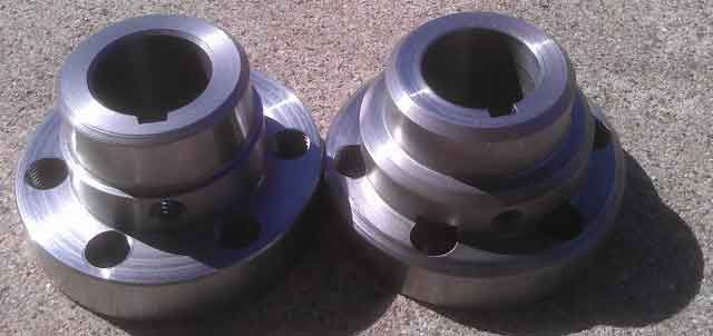
Original coupler on right and revision #2 on the left.
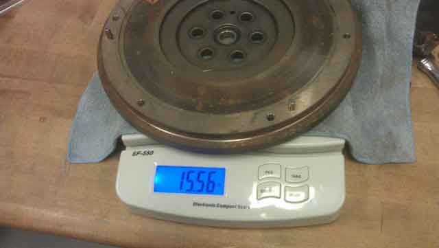
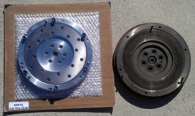
OEM steel Honda Del Sol flywheel weight
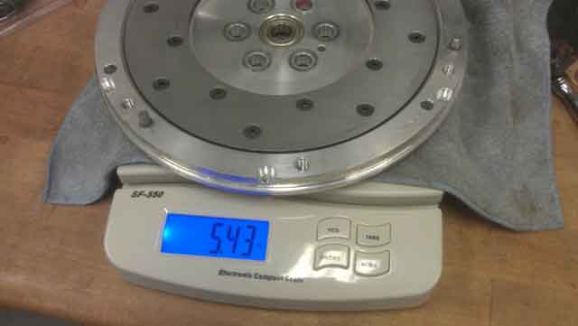
SPEC aluminum Honda Del Sol flywheel weight
Posted: Tue Mar 27th, 2012 01:02 pm
Looks like the machine work is done on the coupler but they
want to double check the fitment before I pick it up.
All this is fine as I have my garage full with another car
project at the moment.
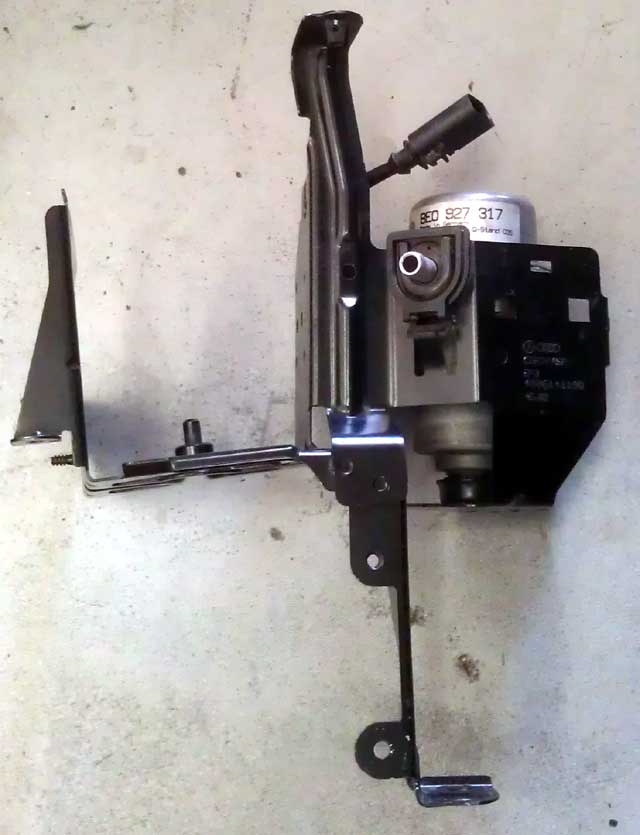
I did find a vacuum pump for the brakes! There are alot of options out there but I like the OEM solution as replcement parts are more readily available. The donor car ws a 2002 Audi A4. $75.00 shipped on eBay.
Posted: Mon Apr 9th, 2012 08:47 am
Update:
Life outside my garage has taken a spin in the last week. This has
affected the time I have to work on this project. The next 4 weeks will
have the same outcome.
Ref: http://forum.smartcar451.com/view_post.php?post_id=2014
The coupler at EVwest is complete but they would really like to put everything together to verify fitment. I think that was just a clever excuse to not have me overtorque something or beat on something with a hammer like an ape and ruin the part. That being said, I will bring the motor back down to them and get everything assembled. When that actually happens is a bit of a mystery at the moment.
Posted: Tue Apr 17th, 2012 01:04 pm
I felt good enough today to at least go down to EVwest and have them fit the coupler on the warp9 motor. The coupler fit on with no problem so I brought everything back and will put the flywheel and clutch on as I find the energy.
While I was there I also got a tyco contactor and a high
current fuse.
I will eventually need the contactor anyhow to switch on the pack voltage. In the mean time I am going to hook it up once I get the motor in and secured just to make a lap around the neighborhood. Just a mental boost for moral if anything else.
Posted: Fri Apr 20th, 2012 09:32 am
The motor is ready to go in the car. Flywheel and clutch are mounted. I spun the motor on 12v to make sure everything was balanced and nothing appeared out of place. Now I must find the time to get it in the car!
Posted: Sat Apr 21st, 2012 01:51 pm
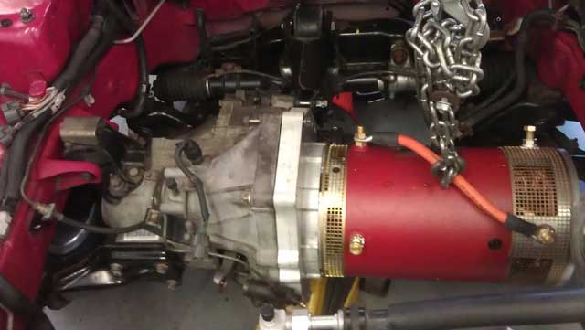
I have the motor all lined up in the car. The bolts that where provided to secure it to the transmisson are a good inch and a half short. Even then with the plates pushed together it does'nt seem like the spined shaft of the transmission went into the clutch. I wont know for sure until I get it bolted up.
Posted: Sun Apr 22nd, 2012 07:57 am
The transmission is indeed not connecting to the clutch. So again, parts come out and go down to EVwest. This time they want the transmission to which means I have to pull the axles and front suspension. No idea on the time frame that will happen....
Posted: Wed May 2nd, 2012 06:55 am
The removal is slow going as I am trying to recover from a motorcycle accident.
I started the transmission removal today with hopes of taking it down to EVWest tomorrow. That now looks like it will be on Monday.
Posted: Thu May 3rd, 2012 12:43 pm
I found time to pull the transmisssion today. I actually got it completed ahead of schedule and figured I had time to run it down to EVwest. However in my haste I forgot to bring the pilot bearing and clutch fork. They slid everything I had together and the transmssion engaged just fine. I will have more to report tomorrow after I bring the remaining parts.
Posted: Fri May 4th, 2012 02:02 pm
Well now that was interesting, or not!
I brought the clutch fork and slave cylinder down to EVWest. They put it together with no problems! I don't know what went wrong with my install attempt. I did leave everything down there and will pick it up next week.
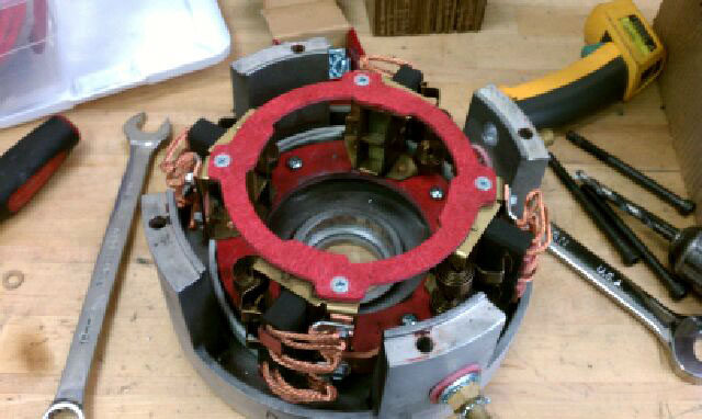
EVwest is also nice enough to install a support brace
they made for the brush holders as well as a set of H60 motor brushes
that I heard are much harder compound. I got these from George Hamstra
@ Netgain motors who is turning out to be one of many quality people I
have found in the growing EV community.
I skipped out on a TESLA event @ nearby "fashion island" today to get the del sol handled. I am glad I did'nt go. It would have only depressed me with my own project.
Posted: Mon May 7th, 2012 02:21 pm
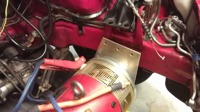
Here is the brace installed. Simple but effective solution to a problem I don't even fully know exists!
Posted: Fri May 11th, 2012 12:48 pm
I picked up everything from EVwest today. They did a great job on the brace install and even needed to bleed some batterys so they used my motor with the new brushes which also help seat them in. They also installed a standard temp sensor in the motor which will make finding a monitoring gauge alot easier. Good job guys!
Posted: Sat May 12th, 2012 02:37 pm
The transmission is back in. I am basically right where I was at 3 weeks ago. Although the 4 main bolts I got from EVwest are now correct, there are 4 smaller bolts need to be longer. Adding to the kaos is that fact that there will be 6 weeks of inactivity on the car as I have other things taking up my spare time!
Posted: Mon May 28th, 2012 05:14 am
Just
a little video of the motor running at 12v. I am going to try and work
with EVwest on getting the endplate mount made. Right now its supported
on the motor side by a jackstand!
http://www.techvelocity.com/misc/delsolrunning.wmv
I also made reservations for this years EVCCON in MO! I did'nt register saying I was bringing a car but expect it to be done by then. That website can be viewed at http://www.evtv.me/evccon.html
Which also brings up the fact that in this weeks show they highlighted the benefits of a new rush material rather then the one that came with my motor. The H60 compound is about 7% more effiecent then the old model of brush grade. The other 7% gain is attributed to the split top design which I did not get. To get the other 7% is to spend $200.00 on HELWIG redtop split brushes. So I got halfway there with the H60 compound of the brushes thanks to George @ Netgain!
Posted: Sun Jun 3rd, 2012 04:56 pm
Ever get so excited that a project is nearing comletion that you frantically get it put together to have same some sort of self redemption and/or the frustration level of the project not being completed sooner gets to you. In my case I just got bored and excited when I realized i had a couple of hours to spare.
It's a mish mosh of a rig job but I got the vehicle to go forward and reverse for a few feet in the garage by jumping a 12v battery. I am still waiting on the rear motor mount, I still need to get the controller mounted and coolng hoses run, I still need a DC/DC converter and a throttle, oh yeah and 160V worth of batteries, yeah thats about it, I am almost done, NOT!
Posted: Mon Jun 11th, 2012 04:52 pm
I decided to remove the A/C compressor and condenser. I did this because that mount plate I am having made for the motor I will have to have remade to include a space for the A/C compressor. When that happens I will also have to convert from R12 refrigerant to R134A which I would have to do eventually anyhow.
In my haste and more likely due to a female hovering behind me, I cut some crucial wires for the vehicle speed sensor (VSS) that are required to run the speedometer and cruise control off the engine harness I was cleaning up. Luckily I had time to use some already terminated wires off the engine harness to complete a factory look. The female in question also felt bad so I got her involved and she helped cover the wires in electrical tape.
I called EVwest and they are still working with the shop to get a plate made. UGG. The specs called for 1/4 steel and they wanted to go aluminum. Since this is just a temporary solution I told them to stick with steel.
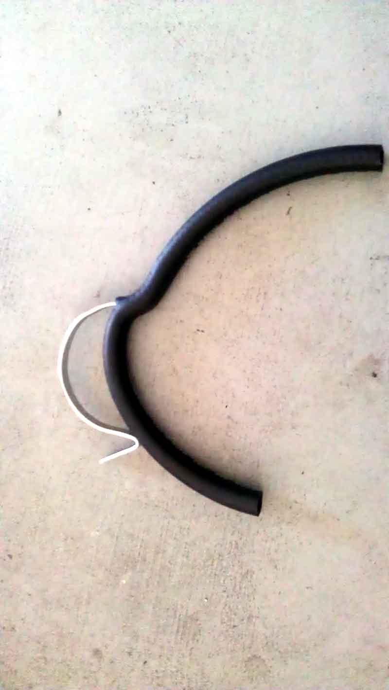
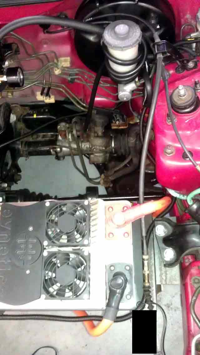
I also decided to avoid certain disaster I am having 12 1/2ft cables made to replace my temporary jumper cables! (remember I mentioned rig job). I placed rubber tubing along the car and routed it in what I though was the shortest and most well protected way I then removed the tubing and measured that.
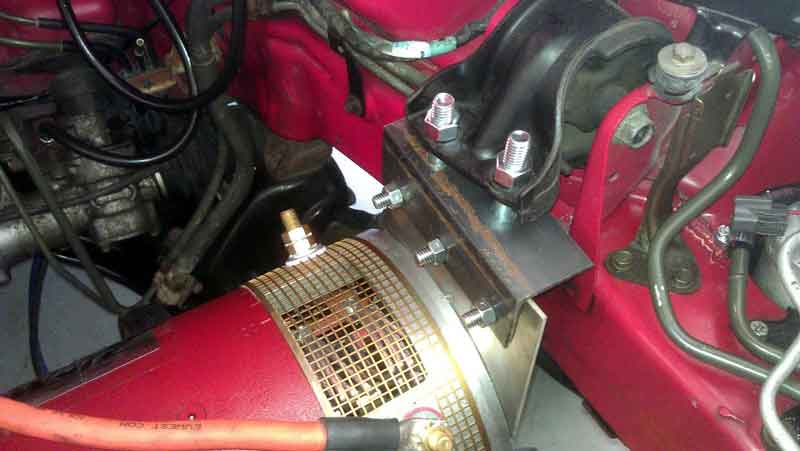
I did think up of a way to mount the Soliton1 controller. I am going to use some angle iron mounted to the transmission bolts. The bolts are long enough to reverse mount the 2 top bolts and then reuse extra thread on the bolt to mount on top of the nut. And if that doesn't work I will just mount it with 1 nut. Mounting it with another nut on top just gives me another inch of clearance. Not knowing how crucial that may be yet. The other end will connect to the motor plate mount.
Posted: Wed Jun 13th, 2012 10:54 am
The rear motor mount is done. I am picking that up tomorrow from EVwest along with a couple odd pieces of angle iron to fabricate a controller mount along with the battery cables. I am also going to see if they have a throttle I like.
Posted: Thu Jun 14th, 2012 05:49 pm
Goodies galore!
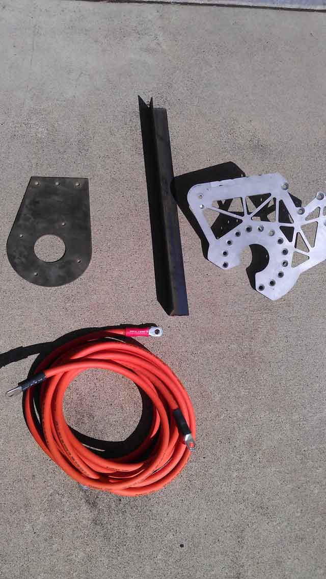
From top left. The motor mount I have been waiting for, some angle iron to make a controller mount, an accessory mount I scored off EVwest to possibily mount accessories, and finally the power cable. I will get to installing as much as I can as I find time in the next couple of days.
I did get the mount installed today.
Posted: Mon Jun 18th, 2012 04:44 pm
I
am pretty sure I can fabricate everything I need to affix the motor to
the factory mount and fabricate a mount for the motor controller on the
transmission/motor using angle iron.
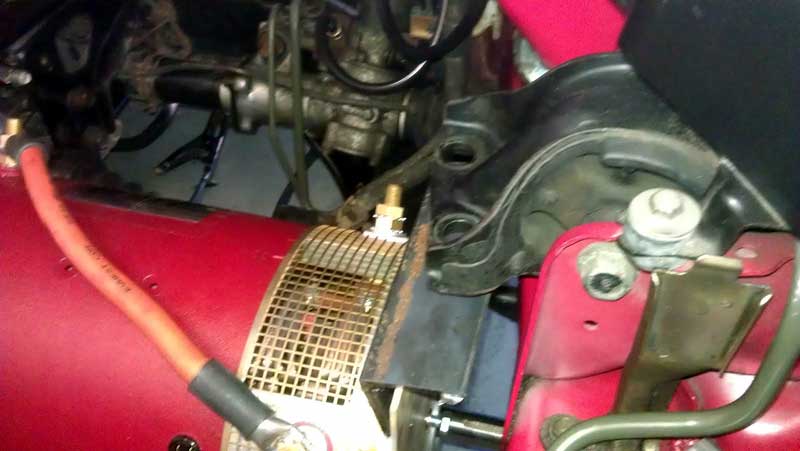
This is my first venture in using angle iron and I am growing a fondness to it. Let me describe my idea and then look at the pictures. The mount on the left side (facing car) is simple. I reversed the bolts for the motor mounting plate so the threads where sticking through the left side. This gives me room to secure nuts on the bolt threads. I also faced the angle iron so it is extending to the left. If I don't need this much space I will simply reverse it the other way. So make the mount more level I also removed some metal from the center of the plate so it mounts tighter to the transmission.
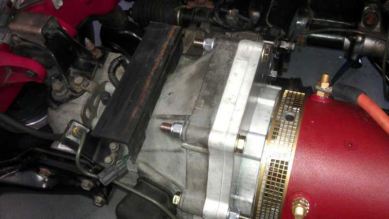
On the right side I am using another piece of angle iron but have to space it out as I the plate doesnt cover both the bolts evenly in the OEM engine mount. I then have to drill two holes and have bolts sticking up which will be secured with nuts in the factory mount. Then behind that I have another piece on angle iron facing the other way to act as a mount for the controller. Hard to explain and the pictures once completed will help. Until then:
Posted: Fri Jun 22nd, 2012 04:25 pm
I have the controller plates on and the mount on the motor. Although I am goiing to redo a couple of the angle iron plates because I want a cleaner appearence.
The distance from center to center of the angle iron is the EXACT distance of the controller mounting holes.
I am getting bolts with a finer pitch on the threads.
Posted: Wed Jun 27th, 2012 06:36 pm
Still fabricating up new mounts for the controller and motor out of angle iron. I have been busy with other projects at the moment. And just when things are winding down and I am about to make the battery purchase news of a revised CALB battery cell is out for the same price. This is the CA series cell rather then the SE. Details of the cells difference can be found on the always informative EVTV blog @ http://jackrickard.blogspot.com/2012/06/battery-jump-shift.html
This would allow be to use 58 130ah batttery cells and still have the performance and range I am looking for (1000amps of power and 100 mile range).
With that in mind I did some measurements for the smaller cells and found I could put 4cells wide and 4cells deep between the front strut towers directly over the wheels. This would total 16cells. I then found I could put 20cells behind the seats on the rear shelf directly over the rear axles.
Beyond that I can put more in the gas tank and the spare tire area for the remaining 22cells (58 total).
Posted: Tue Jul 3rd, 2012 05:11 pm
I remade both angle iron controller mounts and am happy with them. This will allow for as big of a battery rack as possible between the strut towers.
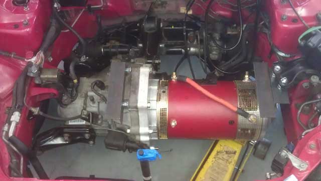
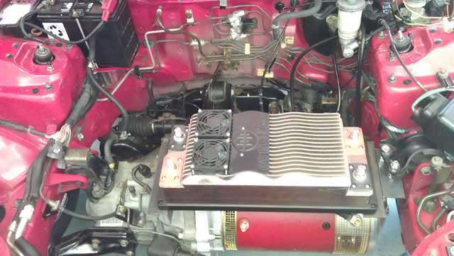
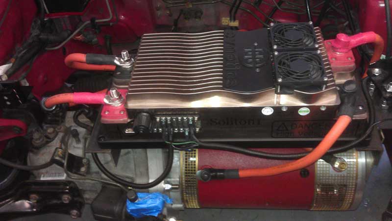
I also fitted the controller and am going to look for some allen headed cap screws to affix it to the mount. I am also going to look for a small rubber bushing and/or washer to provide a little bit of vibration resistance. I am unsure of the controller direction because I am most concerned with allowing the maximum amount of coolant flow and prefer straight pieaces of hose to the controller and heater core. And I have no idea why but that controller looks photoshopped in the picture, I assure you its on there! And on the motor mount I ended up stacking 3 nuts on each stud. This was to prevent modification of the factory motor mount. This way a OEM replacement mount would bolt right in with no modification.
Posted: Thu Jul 5th, 2012 03:12 pm
Yesterday on July 4th I finally mounted the controller and got it wired up for power. I am STILL waiting on a tach sensor from EVWEST to spin the motor up. I have to mount the throttle somewhere and am still looking for a clean installation location.
Posted: Sun Jul 8th, 2012 02:24 pm
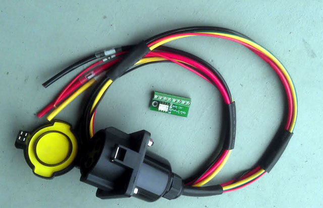
Tomorrow I pick up a tach sensor from EVwest. While I am there I hope to get 2 short cables made from the controller to the motor underneath it. I also purchased a 6 fuse BUSSMAN fuse block and assorted fuses from Amazon. I will use that to provide power to 3 seperate 20amp relays I am going to mount on the firewall. Another small wire will run throught the center console inside the car to a J1772 simulator board which provides the correct handshake signal to turn on most chargers. (Even though I can turn this off in my wall mount GE wattstation EVSE).
This Soliton1 controller continues to amaze me. For having bought this controller 8+ months ago I had feared it may be outdated. True more powerful controllers are out now but this is going to be more then enough for this car. The 3 relays mounted on the firewall will be controlled by the Solton1. 1 for the coolant pump, 1 for the vacumn pump and an optional one for the motor fan if I feel it needs one. This may all get changed around but thats what I am currently thinking. Another idea I had today was running that battery cables through the center console and out holes with gland nuts I would make in the firewall. I had originally planned on running the cables UNDER the car. I am growing more confortable with the idea of them being in the cars cabin. My only concern is the cables as they are routed past the shifter.
I was concerned about the throttle box location as I thought I had to mount a rigid standoff to thread the cables through that would support it as I applied force to the cable. While I am still going to mount a stand off I was happy to learn upon closer inspection of the throttle cable that it already goes through a bracket on the strut tower that provides tight cable support.
Posted: Tue Jul 10th, 2012 02:11 pm
The progression over the last 2 days have been sub par in my eyes. I JUST got the cables today that go from the controller to the motor. (Thanks to Matt from EVwest). But the tachometer was not ready and thus reqiures and extra part to be sent in the mail. On the positive side I estimated the motor cables exactly and are slighty pretentioned in the right position to avoid contact with any metal parts.
Posted: Thu Jul 12th, 2012 11:37 am
That "extra part" I needed arrived today in the mail. Only to find out it is the wrong size. So I waited all this time only to find out I have the sensor for the shaft size I have, IN STOCK the entire time.
So anyways I am wor4ked on the fuse block. The backside iof the block has wiring leads exposed so I made a nice little cover out of spare tinted plexiglass. Rather then try and line of the 4 holes in the fuse block with holes in the plexiglass I just made a large cutout on the inside. It only matters that it seals around the edge anyhow.
Posted: Fri Jul 13th, 2012 05:39 pm
I rewired the backup switch on the transmission so the reverse lights work. I also tapped a wire off of that circuit into 1 of the inputs on the Soliton1 controller. This will limit the power when in reverse. Everything was crimped and had heatshrink placed on the outside inside plastic wire loom. It looks very nice.
I decided to use a piece of angle iron to mount the fuse block on the engine mount. I went into full electrical shock paranoria mode and got nylon plastic screws and bolts to secure it, leaving nothing to chance.
Posted: Wed Jul 18th, 2012 03:41 pm
I installed the tach sensor and updated the Soliton1 firmware. The car now idles but I am looking for a place to mount that throttle and finish up some wire loomes.
I can do small stuff but I will probably hold off on doing anything else big until I get the batterys after EVCON in September!
Posted: Sat Jul 21st, 2012 01:07 pm
Today I finished making the angle bracket to mount the fuse block for accessorys fuses. Adding the first little bit of refinement I decided to throw a quick coat of black paint on it. In the future if I like the look I plan on sending out all the metal brackets to have them hard anodized black. I will put a picture up as I find the time.
The
motor idles off amps but not based on a tach signal. I checked with
EVwest on te wiring diagram and they confirmed my layout as I had
installed it. So I will wait to hear more on that from them.
I confirmed the tack signal is hooked up correctly by telling the Soliton1 controller to have the the #3 output display controller temperature. That corresponded to the tachometer needle indicating about 2000RPM. So I know that is hooked up right.
Posted: Sun Jul 22nd, 2012 06:13 am

The
fuse box all mounted and wired. Just need to get some GOOD (sorry
Harbor Freight) wiring connectors and wire up the individual
accessories.
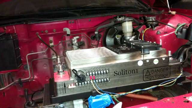
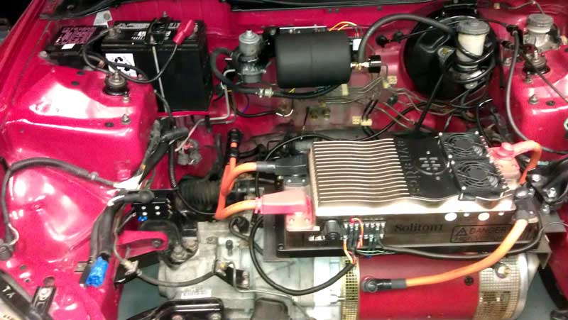
Posted: Sun Jul 22nd, 2012 05:43 pm
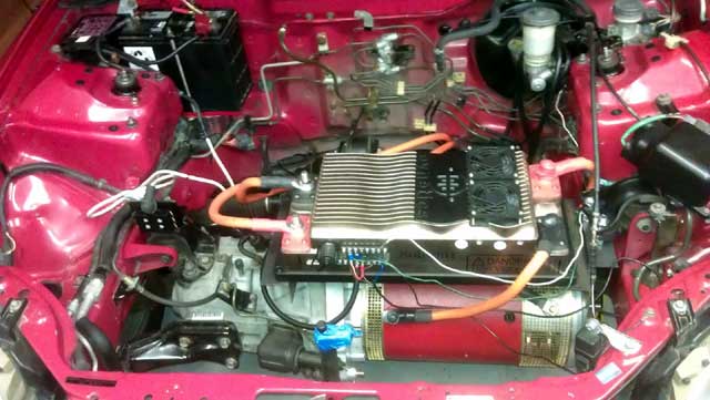
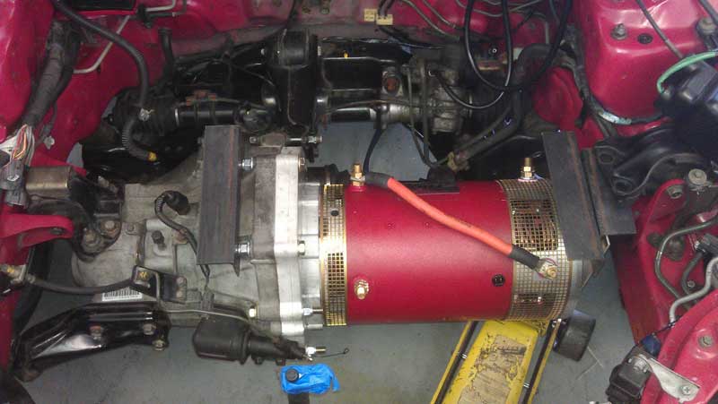
A more up to date photo of the project. The wiring is still rough!
Posted: Mon Jul 23rd, 2012 11:12 am
I made it down to EVwest today. I was able to get the tach sensor tested and it was not working. Matt @ EVwest graciously swapped it out for a working one. I was also able to get a lug for the fuse block cable. I shortened the cable and put shrink wrap on it and it looks great. I have alot of cableing parts on order so when those come in I will wire up the relays to have the Soliton1 turn those on with the controller. OK, enough I's!
Posted: Mon Jul 23rd, 2012 02:10 pm
I couldn't resist! I routed the power cables under the car temporarily (or maybe not?) and took the car out for a test drive! Staying in 1st gear and briefly finding 2nd gear, I made it all around the block which is about 1/4 of a mile. No big deal but it was kind of exciting. Even more exciting was the fact that I was able to get it back in the garage. And the throttle is still not hooked up, I just jacked up the idle to 2500 to drive it around.
Posted: Thu Jul 26th, 2012 03:53 pm
I have cleaned up the wiring alot! Not leaving anything to chance, and even though its only 12v I sealed everything up. On the connectors to the Soliton1 controller I put fork type connectors that have shrink wrap on the connector itself. Then above that I put adhesive shrink wrap over that! And finally the wires are then routed through plastic tubing. I am of course, dreading the possibility of having to rewire and take this all apart but I could only let it look unkept for so long! Beyond that I am waiting for the brake vacumn tank to then complete the fuse block wiring. And I did take the car around the block again just for fun. 24v gets me about 10MPH. And I removed a A/C hard line to give me extra space for the time being.
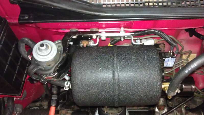
Posted: Sun Jul 29th, 2012 04:52 pm
I
figured out how I am going to mount the electric vacumn pump for the
brakes. I am going to utilize the original Honda fuel pressure bracket
on the firewall. The mount is already mounted on rubber isolators. I am
then going to drill two small holes and use the pump nozzle and a metal
1'' extension on the back to solid mount it to the bracket. This is the
same way VW orginally mounted the pump . I then went to mount the
bracket for the vacumn tank and it ended up hitting the rear
transmission mount. This was to good to be true as the bracket mounted
perfectly with threaded studs that where already coming from the
firewall!
Other then that I am still finding delight in circling the nieghborhood on 24v for the time being.
Posted: Tue Jul 31st, 2012 11:16 am
Today I set off to mount the brake pump on the firewall. This did not go exactly as planned. As it turns out the diameter of the opening was larger then I felt comfortable with just "filling in" with spacers. And with the said, this is where it got a bit creative. I ended up using chrome plated steel bar stock of a new BBQ rack I found laying around. The bar fit perfectly in the loop on the other side of the mount on the car. I will then string a rubber hose through the bar stock and I get the bends and the length correct. There is a moulded ridge in the mount on the car that I will put a piece of hose on that is split up the middle.
Along with that I had noticed long ago the speedometer not working and just got around to that today. I created that harness and so my first inspection point was to verify the wires integrity. All the wires checked out, and all the connections where secure. However when I went to check the wires I noticed the ground wire was a 5V signal. Not knowing if this was correct I grounded it for the time being sandwhiched in between a bolt head and a washer that goes to the frame. Everything I found online indicates this should be a body ground which would be 12v. I will check that on my next "outing" around the neighborhood. I was always unhappy with the way the vehicle speed sensor (VSS) went together when I had it off the car months ago. Worse case scenario a new VSS off eBay is $8.00
Posted: Tue Jul 31st, 2012 12:33 pm
That ground wire was the problem with the speedometer. Everything performs as it should now. Now the question is just ground the wire where its at on the frame somewhere or redo and whole 3 wire harness and ground it closer to the VSS. In testing I made 8 big loops around the neighborhood. I hit an ASTONISHING 20MPH in 2nd gear. (laf)
Posted: Thu Aug 2nd, 2012 01:29 pm
OK before you laugh, this is merely a case of function over form!
I have pride myself with taking the time to have everything laid out neatly and tidy under hood. This one instance however blows it all away (I hope not)!
So I got the pump bracket made, used the
sharper "starter" section on a much larger drill but to start the hole
and then I finished it with the correct size. The chrome surface proved
to smooth and the drill bit wanted to wander. There was very little
room for error as the metal bracket was about 1.5x bigger then the hole
I needed to drill. So that was done and I marked and sliced a hole in a
piece or rubber hose and slid it over the bracket. The pump did not
want to go into the mounted without hitting the metal part of the OEM
bracket. I solution was devised of simply flipping the pump upside
down. But now without the housing acting as a collar the pump could
hypothetically fall out. The fitment was secure and tight enough that I
didn't see this as even a remote possibility but I decided to error on
the side of caution. I took a small rubber strap I had laying around
the garage and wedged it between the pump and the firewall backet. I
then routed the strap under the pump and put tension on it. At this
point with the other end I flipped it over the pump bracket and safety
wired the strap onto itself. I then cut off the excess rubber.
The
pump is powered but a 15amp fuse on my fuse block. The power is routed
through a relay which is controlled by the Soliton1 controller. Right
now I just have it power on with the controller but I plan to hook it
through the vacuum switch on the vacuum tank once I find a place to
mount it. I have also been toying with the idea of having the
controller command the pump relay when the brake pedal is pressed. This
would be AFTER I wire the controller for a brake signal. I had avoided
this because I believe by default the controller is disabled when the
brake pedal is pressed. And right now with just idling around the
neighborhood at 2500RPM I kind of need to depress the brake pedal when
going up the driveway.
The pump is powered but a 15amp fuse on my fuse block. The power is routed through a relay which is controlled by the Soliton1 controller. Right now I just have it power on with the controller but I plan to hook it through the vacumn switch on the vacumn tank once I find a place to mount it. I have also been toying with the idea of having the controller command the pump relay when the brake pedal is pressed. This would be AFTER I wire the controller for a brake signal. I had avoided this because I believe by default the controller is disabled when the brake pedal is pressed. And right now with just idling around the nieghborhood at 2500RPM I kind of need to depress the brake pedal when going up the driveway.
Posted: Fri Aug 3rd, 2012 03:48 pm
I spent entirely to much time today rewiring the main 2 power cables through the passenger cabin. Not happy with the small round plug that the Del Sol has just below the glove box on the firewall, I set off to create my own. I found a nice oval stamped impression on the firewall near that hole. And when I set off to create this I first drilled a large hole and then filed out the space I wanted. This is time consuming but I have learned that although I love power tools, mistake can happen fast! At least this way I have time to correct myself before straying to far. The neighbors where probably taking up a collection for an air grinder as this filing went on for about an hour. And to protect the cables I filed off all sharp corner of the opening and then split thick rubber hose and cut it perfectly tofill in the hole. This is until I get EVwest or someone to cut off the ends by the controller, slide the gland nuts off and slip them on the other side of the cable and then back through the firewall.
I totally spaced on when I had these cables made. I had them put the gland nuts already on the cables, which leaves me no way of taking the nut off to thread them. Then I have the cables routed so that I cant open the center console lid all the way. I fixed this by routing them a different way. However the one thing I cannot fix (I think) is the door for the radio not opening all the way. It comes close and I can operate all the buttons on the radio, but I know it opened farther. I also spent entirely to much time getting grease off of the cables from being mounted under the car.
While I was there with everything opened up I took the time to open the condenser airbox and vacuum out a lot of leaves! I then took a wire through the OEM plug in the firewall and ran a wire to the ECU in the passenger footwell. I am going to piggyback the signal for the brake switch to send to the Soliton1 controller.
Posted: Sat Aug 4th, 2012 11:46 am
Just
for fun I wired up the brake pump to a 15amp ignition feed and took the
car around the block. I now know why this pump is meant for
intermittent use, as it was hot to the touch after the drive. I hooked
up the brake input signal off the ECU to the Soliton1 input and from
there it goes to the pump relay. I little bt of extra wire there but
until I know where everything goes I will leave it. As a positive the
brake switch is always hot so I can leave me foot on the brake before
turning the ignition on and it builds up enough pressure for the first
initial brake depress until the pump comes on. This is all until I
mount the vacuum tank.
Speaking of which to prepare for that I turned the pump around in the bracket (easier said then done) so I had more space to mount that tank right next to it.
Posted: Sun Aug 5th, 2012 04:56 pm
The
pump is mounted temporarly, although it is in the position I plan plan
to use. Luckily I made good use of my vast quantities of metric nuts
and bolts that I have amassed throughout the years! I drove around with
the brake signal I stole from the ECU triggering the brake pump. This
was all yesterday. Then today I hooked up the signal so it goes through
the pump switch before triggering the pump. This circuit is always hot
by default. So this works out good, before or as your turning the
ignition key on, depress the brake pedal and in 3 seconds you will have
a full tank.
I also made a starter cover out of sheet aluminum for the
transmission.
Going through the ECU pinout diagram I found 2 more signals I want to tap into. One being the malfunction imdicator light (MIL) and the engine coolant temp (ECT). I will tap into those in the coming days.
Posted: Tue Aug 7th, 2012 04:25 pm
There
has to be days like this to! Upon finally finding some good 16 guage
wire, I wired up the MIL and the temp guage. In testing however niether
work. I will look into that more tomorrow. I was able to find the
coolant tank that another online vendor uses as part of a cooling
package. They refused to tell me the part number so after a quick
search on Summit racing's website I found the DORMAN part # with a cost
of $6.00. I do have to drill and tap the plastic tank for a couple
barbed nipple fittings but it seems like a small price to pay.
On another note I think I hurt one of my 12v batterys from loading it to much or perhaps it was the cycling that did it. I now have a fully charged pack voltage of 21v instead of 26v. I do seem do remember a small puff of vapor coming from the battery in question.
Posted: Thu Aug 9th, 2012 12:07 pm
I
am a bit confused on the direction I want to go with the coolant
overflow tank. If I where to use it a a "surge" tank like I had on a
couple C5 Corvette's it would require the coolant be under pressure, I
believe 5-6PSI. Unsure if the overflow tank can take that under
repeated use, or even how how this coolant is going to get. And if I
use this as a true overflow tank using the stock radiator is the
coolant EVER going to get that hot with that much coolant capacity to
utilize it.
At this point I am going to hook
up the tank and drill it for 1/2'' fittings drawing coolant using a
larger fitting replacing where the current pipe is molded into the
plastic. I will then put the "return" fitting halfway up on the tank. I
am even rethinking that as I dont want bubbles to be created by the
return that the gets sucked into the inlet pipe. Maybe both fittings
side by side?
And the dash temp guage and MIL light not working may not be an issue. I cannot get the controller hot enough to register a temp @ 24v (well now maybe 20v). And I am not so yet inclined to take a heat gun to the controller so I may just let that go for the moment. I am still unsure if the MIL should be illuminated when I disable the controller. So until a real error come up I dont know. I may try and set the battery rabge out of spec to try and throw a light.
Posted: Sun Aug 12th, 2012 02:41 pm
Just
playing around today. I removed 1 nut from each motor mount studs I had
sticking up for the dog-bone engine mount on the drivers side
fenderwell. This made the motor and controller perfectly level! I am
still leary about how course the threads are but I think it will be
fine.
I replaced the 15amp fuse for the vacumn pump with a 5amp. After repeated use it finally blew. I then went with a 10amp variant and that seems to be holding nicely. The spec called for 15amp but I timed it and the 10amp fills just as fast so I figure less is better.
Posted: Mon Aug 13th, 2012 12:35 pm
Finally got the tank mount finalized. I still wish it did'nt stand off from the firewall as much. The way around that would make a longer plate and bolt the tank directly to that. It would be off center by a couple inches with no support behind a portion of it.
Posted: Sun Aug 19th, 2012 07:37 pm
I
shortened up a few wires under the hood (I can't call it "engine bay"
anymore) and re-routed them for a more cleanly appearence. I am going
to try and get the small pin blade type connectors from a local Honda
dealer so I dont have to splice together to a pre terminated connector
wire. I did end up grounding the VSS locally to a ground bank on the
firewall and avoided a long wire connection.
And I did find another place for the vacumn tank if its current location does not work out. Yes, it involves the use of more angle iron, WAHOO!
Posted: Mon Aug 20th, 2012 01:28 pm
I think I know how I am going to route the throttle cable! Yes, it involves angle iron. I am going to make a new motor mount and extend the angle iron out by about 5 inches (Black rectangle in photo). This is the best solution I have found. In doing this it does not bend the cable any more then stock. It will also require a very short run of 14-15 inches of wire to the controller.
Posted: Tue Aug 21st, 2012 02:45 pm
I had time to kill today so I tried to figure out what's going on with the service engine soon light, more specifically, why it is not illuminating. It dawned on me it is not I wise idea to piggyback this wire. As when the Soliton1 commands a light it is now connecting it to a output on the ECM. I think the first matter is to disconnect it from the ECM while keeping the wire from the controller attached.
I am trying to get a different and smaller throttle assembly. I am wanting the EV Netics throttle at this point. I am going to try and get this through EVWest.
Posted: Sat Aug 25th, 2012 01:38 pm
Ahh yes, well then. The relocation of the vacuum tank closer to the firewall didn't work out. After I made a simple bracket out of steel I went to mount the tank and I couldn't even get a couple threads one, the tank was hitting a brake junction on the firewall. So the location quest continues. I found a great spot but I don't know if its a wise choice. I used a piece of scrap angle iron (wahoo) and mounted it on the motor plate/transmission. How much vibration this will receive is unknown. Right now it remains an idea.
I also removed all fuel and vent metal hard lines going back to the fuel tank. Gone are the ideas pumping mineral oil into the OEM fuel tank to cool the controller, hey it was an idea.
I am also very close to removing the power steering lines. I think leaving fluid in them not needed at this point. I don't even think I am going to bother with removing the internal seals from the rack to prevent build up of pressure, it feels great.
Still looking for OEM Honda pins for my shortened VSS wire.
I came across 2 more Diehard 12v batteries! But until I get a throttle I am only going to hook up 2 for 24v. But once I get a throttle look out for 36v of untamed heart pounding acceleration, or NOT!
Posted: Tue Aug 28th, 2012 02:48 pm
One
of those 12v batteries was bad (I swear I didn't do it). I have now
limited the output from the Soliton1 to 40amps from the battery so that
should preserve things while I am playing around.
I still have a few things to do but "other" things are keeping
me busy.
One
thing I want to get is new OEM Honda rims. This model Del Sol being an
"Si" came with 14inch tires. Unfortunately alot of of rolling
resistance (LRR) tires are available in 13 according to tirerack.com.
13inch tires where standard on the "S" model Del Sol so a quick
comparison using the tire calculator from Miata.net which I have used
so much over the years I now know by heart, shows a near identical
circumfrance. The 14inch rims I have now are lovingly referred to as
fat 5's because of the wide spokes. Looking around I noticed a lot of
Honda's use a similar wheel offset of 45mm. I found the 2 lightest rims
Honda makes are the Civic VX for 13inch (9lbs) and Civic HX for 14inch
(11lbs). This all from the 92-95 Era. The OEM wheels I have right now
are 16lbs with no tires. A 28lb reduction would be HUGE! So add to the
list of things to be on the lookout for. For tires I like the Michelin
Harmony that carry a UTOG (overall hardness) of 740! This while most
sporty tires are about half that.
Specification Sidewall Radius Diameter Circumference Revs/Mile
Difference
185/60-14 4.4in 11.4in 22.7in 71.4in 887 0.0%
175/70-13 4.8in 11.3in 22.6in 71.1in 891 -0.4%
Posted: Thu Aug 30th, 2012 07:15 am
I found a great place for the switch for the J1772 simulator board. It's the hole for the fuel door latch. Its near the same size as the hole that was already there. To fill up the space and make mounting alot easier because of the nature of the thin retaining nut, I cut a small piece of smoked plexiglass to act as a collar. I threaded the plexiglass with a tap to make it a very secure fit. I also removed the spring on the fuel door so it closes flat without issue. The switch is off when down. When I want to recharge the car I move the switch up and connect the J1772 plug from the GE wattstation EVSE.
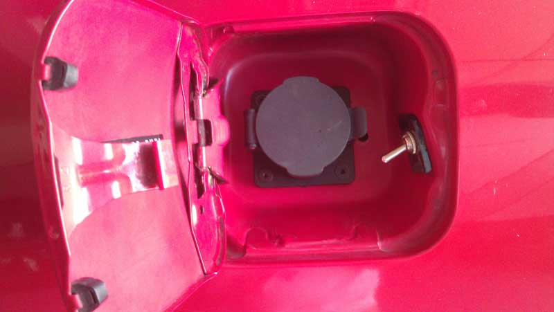
Just
waiting on the throttle to come in from EVwest at the moment. I found a
used manual steering rack just surfing the internet for cheap, still on
the fence about that.
A local auto parts place I know will sell me used 12v batterys
for $8.00. I might pick up a few more to play with.
I will disconnect the SES light and ECT sensor wires from the ECM in the coming day, hoping for good results!
Posted: Thu Aug 30th, 2012 12:25 pm
Found
time to work on the car. I had planned on leaving the ECU connected and
just remove the PIN for the ECT and SES light. I could'nt find a small
enough piece of metal to aid in the removal of the pin so I just
removed the whole connector from the ECU. I then powered everything up
and the SES light now works! I went ahead and removed the 3 main plugs
for the ECU and took it out of the car. That's 15amps I would prefer
not to have draining the 12v batttery. Unknown if I will need the ECU
to enable cruise control or not, I will look into that.
As
far as the temperature guage goes it still APPEARS not to be working,
although I won't know for sure until I get some serious voltage through
it. I wont if the ECU calculates the ECT and then sends a signal to the
guage? Perhaps I need to wire it up to the ECT sensor wires that where
originally underhood on the motor? Just spinning wheels at this point.
I think I will hold off until I get more power through it.
I had originally thought about running the main contactor through the fuel pump relay circuit. But now that the ECU had been taken out, that will be a seperate wire run. Besides that I can think of a couple variables where the ECU might not command the fuel pump to be on.
Posted: Wed Sep 5th, 2012 04:18 pm
Still
waiting on the throttle from EVwest (they either have an incorrect
tracking number or EVnetics has not shipped it yet). I will know more
tomorrow.
Other then that just waiting on more connectors to show up so
that I can finish the shortened VSS and tachometer cables.
I am liking the CALB 100AH CA series batttery cells at the moment. I could do the 180AH cells but finding a place to put 58 of them would take up alot of space.
Posted: Thu Sep 6th, 2012 01:28 pm
The throttle is MIA and I don't know who to believe. Latest word is maybe next Monday and Tuesday for sure.
Posted: Wed Sep 12th, 2012 08:19 am
I have the throttle. I went down to EVWest and picked it up yesterday. I hooked it up and love the design. It is not mounted on the car yet which will require the recreation of a motor bracket (wahoo angle iron fun). Good thing I have'nt painted anything yet! At the same time I can put a smaller bolt in one of the motor mount holes that I have been meaning to do. I leave for the EVCON electric vehicle convention in 10 days and am pretty excited!
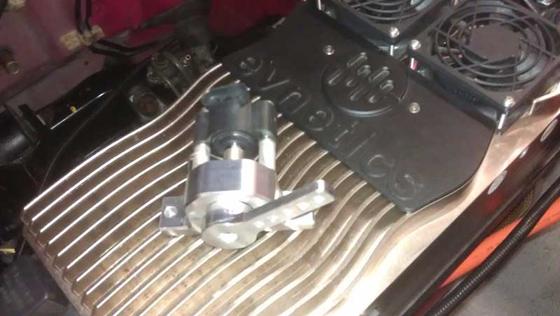
Lot's of things going on outside the conversion is going to keep me busy for at least a month after I get back from MO. All fun stuff!
Posted: Thu Sep 13th, 2012 03:52 pm
Today
I removed the controller and existing metal mounts and cut a new mount
for the throttle, painting it along the way. The other mounts will be
trimmed up, cleaning up area's that may rub up against other wires.
Then I will file the metal edge's down and paint them in black enamel
paint before reinstalling them. I had thought of anodizing them black
but in the effort to get things done quickly (aka I am impatient as all
hell) I just rattle canned it. I was going to do this at some point and
now is the best time. From this point forward it will only be more
difficult working around large battery boxes.
I have finally settled on the goal of 58 batteries with the following arrangement. I will have 8 mounted in a box that goes inside the fuel tank shell so that I can use existing straps. The tank is not that heavy and I don't want to draw attention to a shiny aluminum battery box under the rear bumper. Then routed to 40 behind the seats inside the car on the existing metal shelf. Which will be 3 rows of batteries 8 wide. Then on top of that 2 more rows of 8 wide. By having 2 rows on top I will have space to put the seats all the way back on the seat rails with more then enough recline. Then its routed back underhood to 2 rows of batterys 5 wide mounted in a box on rails between the 2 strut towers.
Posted: Fri Sep 14th, 2012 12:59 pm
Today I painted all the mounts and created a throttle cable bracket. The OEM Honda motor mount has a raised hump of metal between the two holes. Rather then creat a bracket with a nothed out portion, and because I needed the engle iron to be facing front to back of the car I created one. Because of the length of the angle iron I could only utilize one bolt hole. Here is where it got creative. To support the metal bracket I notched the bracket just enough so that it take some force to slide it in. This way even if the nut on the bolt came loose, it can't go anywhere. I will try and mount everything tomorrow!
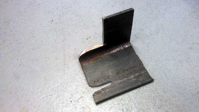
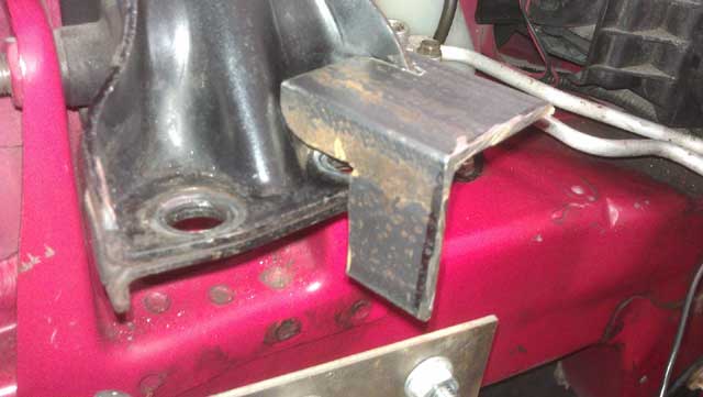
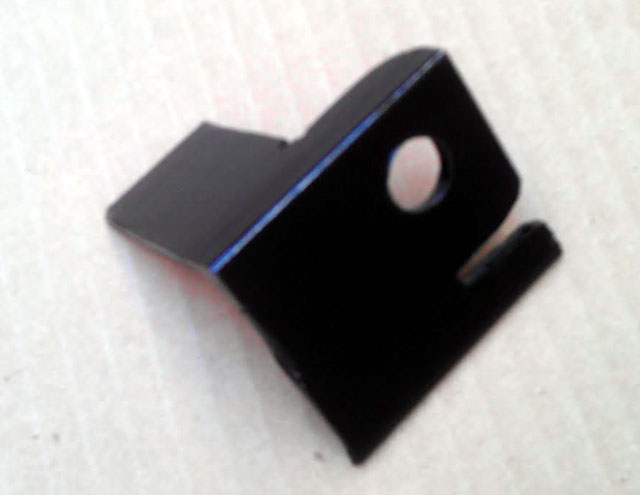
Posted: Mon Sep 17th, 2012 03:19 pm
The best layed plans,.....meh!
The
bracket I had made and painted did'nt work out. I failed to realize the
mounting angle of the bracket was to low to make a clean sweep of the
throttle.
So I created a new one and painted
it, I will install it in the coming days. I am also busy trying to find
a way of connecting the OEM weight on the throttle cable to this
EVNetics assembly.
I do have the throttle mounted on the plate however.
Posted: Tue Sep 18th, 2012 03:20 pm
Today third time was not indeed a charm. For it took 4 brackets to get one I was happy with. I am happy to report the throttle is hooked up and working. I shortened the tach sensor and throttle wiring to exact length. Other then painting a bracket it is done. Of course I see a couple things I could make better so even this may be temporary.

Posted: Thu Sep 20th, 2012 02:13 pm
Throttle is on, mount is painted, calibrated in the Soliton1, extra 12v battery added (for 36v again) and I have limited the amperage to 100a. The motor now free spins to 4,000RPM and hopefully I can get some heat built up in the controller to see if the temp guage is working.
Posted: Sat Oct 6th, 2012 09:58 pm
I
have returned from the 2012 EVCCON event and various traveling across
the country, about 5,000 miles worth. This years event was different
then last. The time the speakers got was more limited and didn't a lot
them time to go into detail about their product/services. HELWIG
brushes was a great example. Last year we got detailed instructions on
replacing the brushes and trueing the COM on the motor. I will perhaps
revisit this post in the the future and go into more detail but time is
short right now.
Other reflections on the
event. Everyone I met at the event was a stright up person. Which leads
me to wonder how people get ripped off in this industry. To combat this
EVTV is going to setup a "preferred vender" list to help prevent this.
Sebastien
Bourgeois from EVNetics and Rebirth auto was on hand and brought his
Porsche which most of the attendants had seen from last year. He made
me an offer on an upcoming charger/DC to DC converter that I could not
refuse so it looks like I will get that from him. In the meantime I
will be using an ELCON PFC2500 that I am borrowing. Sebastien is
another good person I remembder from last year. I do hope this year
provides him the sales and emotional drive it is going to take to
sustain and further his business.
John Hardy
was there with his book "ICE-FREE" which I bought and had him
autograph. It's strange but I won't have time to read it until after
the Del Sol conversion is done. I do hope I am wrong though!
Beyond
that the host Jack Rickard seemed tired and drained in the remaining
day of the event. I really want to see this event succeed. A lot of
returning cars where at the event. And of the new vehicles on display
they where much higher caliber conversions. It made me feel better
about taking the extra time on the Del Sol, nothing goes unnoticed.
I
will take the next few weeks to tame the visiting girlfriend I picked
up from out of state on the trip and hopefully get some battery boxes
made.
Latest underhood shot:
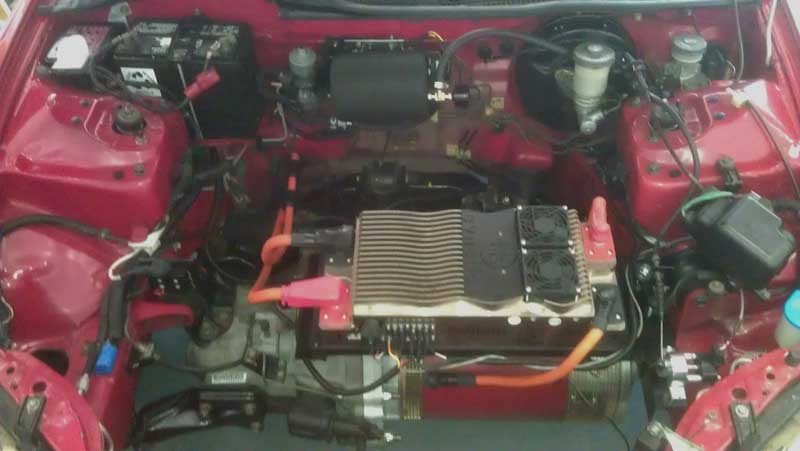
AVC2 module that David Kerzel from Modular EV Power was nice enough to enclose in a box! David is an educated man and his EV business thrives on his knowledge of IC's (Intergrated Circuits) and product packaging. He is one of those business's you really want to see what products are around the corner!
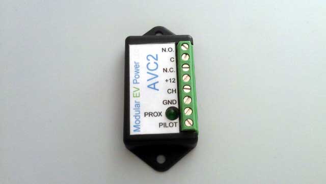
Posted: Fri Oct 12th, 2012 03:44 pm
I contacted EV West today and gave them the specs for one of the battery boxes I want for behind the seats on the shelf that previously housed storage bins. They wisely advised against making one until I had battery but I assured them I had exact measurements of exact batterys. The battery box is 8'' x 44.75''. It should house 3 rows of batterys running 8 cells wide for a total of 24. I am asking them to make the battery box with enough room at the bottom to bolt directly to the floor while alowing a bottom to be placed in the battery tray to cover over the bolt heads and provide a smooth surface. I already know I will have to cut some plastic trim pieces to allow for the width. And I also got the storage trays torn down to cut them at a later date. Now off to find more boxes to have built...
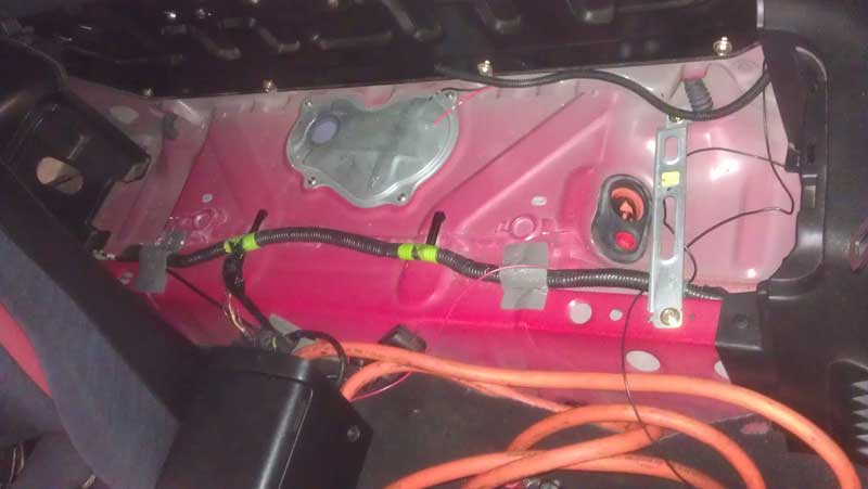
I also ran a 16ga wire from the fuseblock with a 3a fuse to power the AVC2 J1772 module.
Posted: Sat Oct 20th, 2012 11:14 am
In
yet another case of dumb luck I remembered I had the long battery
cables terminated with the smaller battery style lugs on one end. This
is the exact same size I will need for the batterys.
I
should have the interior battery box made and picked up during the
week. EVWest was pushing to have all the battery boxes made at once to
"save time and cost on setup", but I did'nt bite. If the cost is
anywhere near what I was quoted to make then 1 I am going to make the
other 2 battery boxes out of milk crates!
After ALL THAT WORK fabricating up a mount for that vacuum tank I might move it to another location. This will allow another row of 5-6 batterys to be mounted between the strut towers. Oy Vey!
Posted: Mon Oct 22nd, 2012 04:30 am
This
weeks EVTV episode metioned a SAE standard for DC fast charging had
been finalized. He also mentioned that it would be between 200-500v DC.
This negates alot of smaller battery packs using by home conversions
which makes me feel better about a 58 cell count I have long been
leaning towards. This (in theory) gives a charge voltage of 203v or
58x3.5v. Taking the advice from Jack @ EVTV to undercharge the cell and
not over discharge when in use.
I also like
the bedliner coating idea on the battery box mentioned in this weeks
show. This gives it a nice rough black textured finish that can take
some abuse. Providing this does'nt add a measureable amount of weight
this may be my course of action above my idea of hard anodizing it
black.
EVTV featured the Powerlab8 battery
charger/discharger used in the R/C hobby market a few weeks ago and it
looks like they just added it to the online store. Although more
expensive then the simple solution of hooking up a drain resistor to a
single battery cell, you dont have to worry about babysitting it and is
fully automated.
Oh yeah.....and another thing.
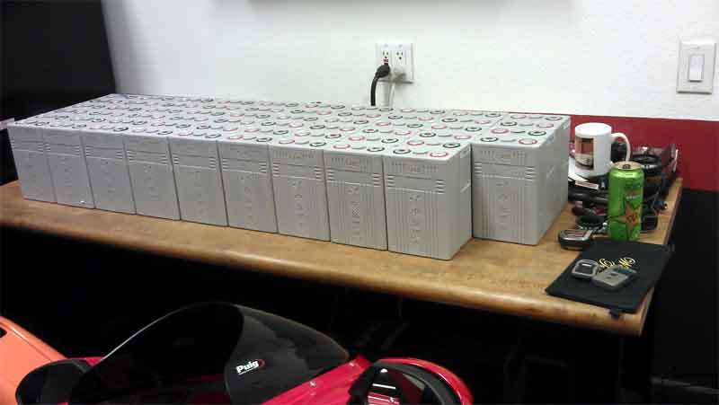
I
have batterys! About a week before leaving for EVCCON in September I
drove to CALB in Pomona, Ca to pick them up. Luckily living in SoCal
saved on shipping! I picked them up from the most non-descript
warehouse in history right next to a freeway. I also met the now
infamous Keegen @ CALB batteries who is very friendly.
The
batteries are the new CA series (or grey cell) in 100AH capacity. I
felt that size battery was the limit of how much space I could use in
the car to stuff 58 of them in there. It has, nor ever will be my
intention to turn this car into a non-usable person mover with no
storage for groceries. I have a couple of those already, its called a
motorcycle! The batteries came with a spec sheet on each cell that
range in capacity from 108-112AH. And knowing your pack is only as
strong as your weakest cell, that makes them all 108AH. But seeing as
they are advertised at 100AH its like I got 2 more batteries for free
with a count of 58 totaling 6264AH.
So exciting times, but another piece of the puzzle that will only try my patience as I am tempted to run on 76.8v with just 1 battery box complete in the coming week but I will resist!
Posted: Sat Oct 27th, 2012 01:05 pm
So
it took until Friday until the box was ready to be picked up from
EVwest. They say it was the place they contract out through but I have
my own idea's.
I tried installing the box
today to discover it was taller then originally thought. This is my own
fault. I remember EVwest saying they make the box taller to allow for
gland nuts for wires and lids for the batterys. This now means I will
have to relocate the rear speaker placement. For the time being they
are simply removed. I did not feel good about this but felt I had no
choice. I also tapped an existing threaded nut I found unused in the
center under the car where the exhaust went. I will use 1 bolt and a
supporting ziptie until the vehicle is mobile and I get that vacuum
tank bracket tack welded on. I also finally found where I am going to
mount the shunt to measure current and report to the JLD404 meter I
purchased from EVTV. It will be located directly to the left of the
Soliton1 controller. Sadly no amount of angle iron would allow the
creation of a suitable support bracket. I will have a plate of steel
welded to my existing bracket for the Soliton1.
The 1 box for behind the seats came to $500.00 for what looks to be a simple box. I am going to need at least 1 more, maybe 2. The thought of another $500.00 per box got me to source the boxes to be made elsewhere for about 35% percent less! And yes, EVwest was less then happy I got the batteries from someone else and not them. It came down to a price point and business I want to see succeed.

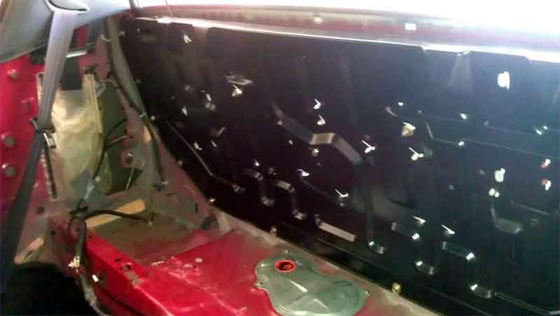
Posted: Tue Oct 30th, 2012 05:00 pm
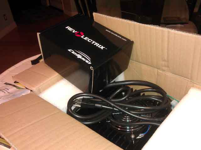
More
goodies have arrived. The Powerlab8 battery workstation and a PFC2500
Elcon charger. The charger is loaded with charge curves from 51-61 cell
counts. Using the cell count number I can adjust the charge voltage.
Right now I have it set for 3.53v per cell which I believe to be near
optimal for cell life longevity.
I was able
to get a plate welded to my existing contyroller mount for $45.00 and
so I am set to clean and paint the mount. After a couple days drying I
will then mount the shunt with the same plastic nuts and bolts I found
at LOWES to keep everything isolated.
I am getting a more firm quote on the second battery box sometime this week.
Posted: Mon Nov 5th, 2012 02:39 pm
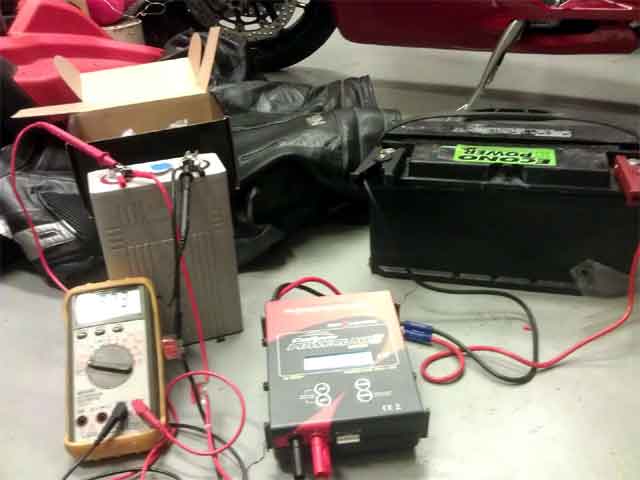
I
am officially having more fun with the cellpro Powerlab8 that I
purchased from EVTV then should be allowed! I am finding old battery
packs I am able to put a slow charge and drain over how ever many
cycles I want. My best revival to date is a 20yr old TYCO 9.6v turbo
hopper NiCD pack that had 13mAh registering when I first hooked it up
to the now 900mAh that is going in now. I could do this all day
Now one of the pack presets I had selected wrong and it began charging this one cell to 4.2v but I caought it in time before damage to occur. This one cell has become a sort of test cell as I have been less then kind with it.
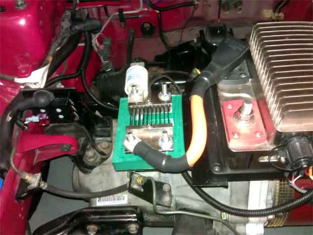
Rather
then drain each battery individually from its current state of charge I
decided its best to put them in the car and drain them with the motor.
That means hooking up cables and FINALLY installing a shunt and the
famed JLD404 meter readout. I used my favorite nylon bolts I got from
LOWES to sucure the shunt to the mounting plate.
All
the battery cables are out of the car. The box is awaiting the rock-it
spray on bedliner I ordered from Amazon and it ships locally so I may
get it tomarrow. From there I will acid etch the battery box to prime
it for coating. After that I will install the battery cable and take
the box down to EVWest since I lack the proper crimping tools myself.
And try as I might, I could not find a viable reason to make anything out of angle iron!
Posted: Tue Nov 6th, 2012 11:36 am
I
weighed some items today. The aluminum box is 26.91lbs, the plastic box
bottom is 8.16lbs. Combined with 24x 100AH cells that will be about
202lbs for the largest box.
UPS delivered some ROCK-IT bedliner and primer I will attempt
to coat the battery box with.
I contacted EVWest and setup a time on Friday to have the
cables crimped.
10 days until the girlfriend leaves back home and progression can happen at a more rapid pace. Is that PC enough?
Posted: Fri Nov 9th, 2012 02:56 am
I
have not found the time to paint the box yet to prepare it for coating
and then to EVwest for cables! This will happen in the coming days.
I am actually amazed I got the shunt plate made and installed as I had said a while back I had a girlfriend from out of state visiting me for a month. This comes to pass in a few days and I look forward to the progression!
Posted: Sun Nov 11th, 2012 02:19 pm
Misc
notes: As I am charging 24x cells independently so that I can monitor
and learn the charge curves visually (makes for boring work). I would
have to recommend at this point to chase the threads of the cells
(8x1.25mm on a 100AH cell) tyo ensure easy fitting. It's only the
negative soft copper terminal I have had issue with. It's generally
good practice anyhow. I am currently halfway done with the initial set
of 24.
As far as mounting the rear box is concerned I am reusing a large metal collar from a 1989 era Kawasaki Ninja 250 motor mount that fit's the bill nicely. I cut the collar down, put a large metal washer to distribute the load evenly. The bolt that goes through the collar however does not have enough metal through the sheet metal to be firmly affixed.
![]()
There is however to smaller bolt holes located within a close proximity that will be used. I located 2 large 10mm bolts from the extra parts from the engine removal that fir perfectly. I tapped 2x 10mm bolt holes that had extra metal beneath them that will work nicely. I cannot get a nut underneath the main bolt with a collar due to a rather crucial suspension bracket being located directly beneath.
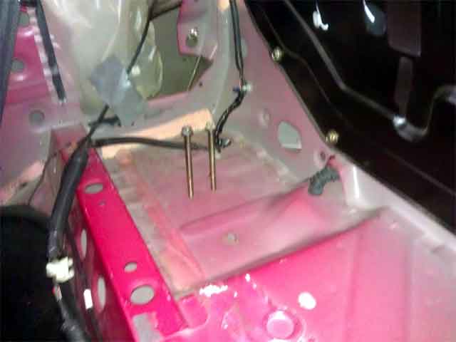
I then drilled holes in the false bottom I have for the
battery box to allow space for the bolts heads I am using to secure it.
Along
with that come the fact that I mistakenly ordered the bedliner with a
tintable base and not black. Luckily this Amazon.com order was
fulfilled by a vender located in San Diego and I made a nice day trip
out of it.
So as soon as I can get that box painted and coated I will. Then off to EVWest for the cables.
Posted: Mon Nov 12th, 2012 03:26 pm
Here
is how I am. I can be very patient but it gets to a point (usually
close to completion of a project) when I get overly excited and rush
things. 2 things can happen when this is reached. 1. I injure myself.
2. I make a costly mistake. Luckily none of those feats where reached
today. I mounted the box behind the seats, it is unpainted. I also made
the decision to slot the holes in the box for the battery cable gland
nuts so that I don't have to bring the box down to EVwest and get the
cables terminated connected to the box. This whole "rush job" came
about because I promised my girlfriend a ride in the car before she
goes back home on Thursday. I had plans on doing this just around the
local street on 3 12v lead acids batteries but am glad to do it on 76v
of CALB batteries. I do still need a cable terminated with a large lug
for the controller which I plan to get tomorrow.
I
have 18 batteries charged to 3.5v. I only need 6 more for this box and
then I can go play. Knowing of course I have NO charger for the smaller
pack and have to charge them individually. And the going charge time is
just over 2hrs @ 20amps per battery, it makes for boring work. I will
monitor the current usage on the JLD404 meter and use that as my gas
gauge. I plan to limit myself to 1440AH of use, 60AH per cell. Playing
it safe.
I am curious how fast the car will go. Napkin math indicates 45MPH, range of 20 miles. Anyones guess at this point.
Posted: Tue Nov 13th, 2012 02:45 pm
The car is cobbled together enough to attempt a trail run and fulfill the promise. Hopefully it will be uneventful. EVwest was kind enough to terminate the battery cable today and I finished everything up just now.
Posted: Thu Nov 15th, 2012 09:41 am
Well
that went of without a hitch. The car was complete ehough to take to a
local restuarant for a meal! Thereby fulfilling my obligation to the
girlfriend.
The vehicle will go about 55MPH and I start the car in second gear. I do notice if I give it to much pedal it will slip the clutch ever so slightly. Unaware if this is due to the aggressive throttle slew rate setting or the clutch not being bled. I will look into that in the coming weeks..
Posted: Thu Nov 15th, 2012 02:11 pm
Charging
stations are becoming more main stream. The first DC fast charger from
I think from ChargePoint recently opened up 7 miles South of my in San
Juan Capistrano at a motel alongside the 5 freeway.
After
putting more miles on the car at higher speeds I have determined the
manual steering rack with its higher steering ratio would be the best
choice. There are a few remanufactured ones sold on Ebay but I happened
to find a line on a nice used unit. It's best I swap the steering rack
out now before I cover it with batteries!
I
also found a better way of arranging the batteries. Rather then have
the cable come into the box and mount to the battery less then an inch
later I am going to reverse the battery and have it go across 1
terminal to allow space for a gland nut. Not sure if this is a wise
move. Hey whats the worse that could happen? Nevermind!
Dave if you plan on converting a car someday I would be happy
to help.
In
other news.....if you believe it, the US is supposed to become energy
independant by 2030. They fail (as do most Americans) to realize this
drilling for more oil does nothing to deal with the emissions they
produce.
All this while BP has today agreed to a record 4.5 Billion
dollar fine for the 2010 Deepwater Horizon oil spill.
Also Homedepot.com now has 30 different chargers available for electric vehicles!
Posted: Sat Nov 17th, 2012 04:12 pm
While I await the steering rack I decided to revisit some
problems.
1:
The gland nuts on the battery cables where to high on the box to allow
even mounting to the batteries. My mind was abound with crazy ideas.
Fill the space up with washers on the bolt, grind the hole in the box
1/2" down and slide the gland nut down, etc. After closer inspection of
the other cable end I noticed I had put thinner heat shrink on that
side. I slide the gland nut up and presto! It fits perfectly. The holes
are indeed in the correct position and it was the thick heat shrink not
allowing the cable to articulate (+5 SCRABBLE pts) downward.
2:
I thought the rear plastic panel below the rear windows would have to
be trimmed. I don't know for sure yet but it looks like I will fit
unmodified. I had plans of covering the area with DYNAMAT because it
would have no sound absorption. I did however decide on covering the
floor beneath the battery box with DYNAMAT. Mostly because there are
some holes from the gas filler tube and fuel pump wiring that I only
plugged with some cheap pieces of plastic. I will also cover the walls
where some cheap OEM plastic splash guard was covering the area. This
may be uncovered for a while as I make revisions to the car so I want
it quiet.
I made the changes to the Soliton1 controller that should improve the throttle application and not make the new clutch slip.
Posted: Tue Nov 20th, 2012 04:45 pm
Again, I could forgo this post in its entirety because it adds
nothing to the saga.
The
24 cells that I have been using are all charged and topped off. Each
cell consistantly took 32amps to reach 3.5v. With the exception of ONE.
When it went past the 40amps in mark I knew exactly what happened. But
never the less I grabbed a bag of popcorn and for 30 minutes I was a
shivering *itch. It finally reached full at 72amps! Just over the 70%
discharge rate I did'nt want to break. And honestly even now I may not
have broke that, remember the weakest cell in the pack of 58 is
108amps, so its not even worth breaking out the packing list and find
out the specifics. So my bad on that one which could have killed a cell
but luckily I was playing it safe and only discharged 30amps from the
pack. I blame the double D equipped girlfriend that was parading around
the garage during the process.
Then I went
through all the cells again and topped them off with another 700-800Mah
of electricity. With the exception of ONE. This cell took 32amps. I
guess I missed one on this round to! With the garage vacant besides
myself I had noone to blame, I knew I kept her around for a reason!
As
to why the JLD404 meter indicated 29.95amps drawn and it took 32-33amps
to fill up is acceptable at this time. I used the motor for testing
without the meter hooked up after the batterys where charged for a
little while, Charging inefficiency, etc.
Still waiting on the steering rack and Dynamat.
Posted: Wed Nov 21st, 2012 11:45 am
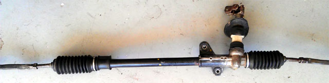
The manual steering rack has arrived, it is just what I wanted. There is a smaller U clamp for the body housing mount (visable all the way to left) because the body is smaller for the manual steering. So rather then sandwhich some rubber in the existing bracket I just went to the dealer and ordered a new $10.00 bracket and associated spring bolts for manual steering. It should be here Friday. I may wait until then to start removal of the power rack.
Posted: Thu Nov 22nd, 2012 12:37 pm
Luckily to to scheduling confilcts I am celebrating
Thanksgiving on Saturday, that meant garage time!
I installed the new rack. I had to drop to subframe, but not removed it. And the front right tire is off camber so I shouldn't of trusted where the tie rods where placed on the old rack. But, its in!
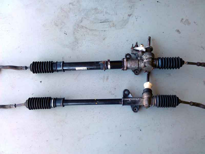
The larger power steering rack is up top. I am still awaiting the U clamp from Honda.
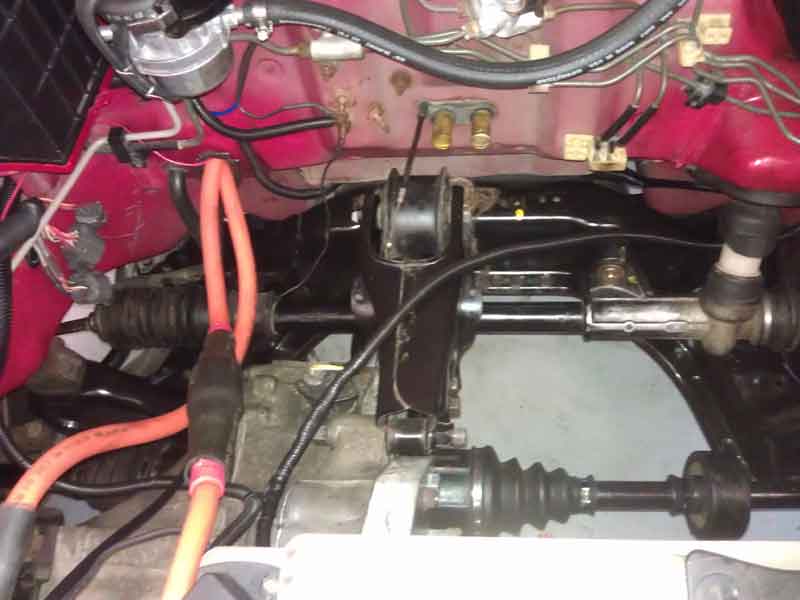
The cleaner installed look!
Posted: Thu Nov 22nd, 2012 02:20 pm
One
more thing. Missing charging that one cell bothered me. So I went
digging in the charge log reports. Turns out, without noticing it, I
hit an error 97 on that one cell which turns the charge cycle off until
the cables cool. The other cell that took alot more voltage was the
cell behind the cell that hit error 97. So I did'nt forget to charge
the cell, it just got the cables to hot @ 20AMPS and shut off. Either
way I just need to pay more attention to the charge cycle.
And the front right wheel is WAY off alignment. I will try and eyeball adjust that tomorrow for the time being.
Posted: Fri Nov 23rd, 2012 01:49 pm
I eyeballed the alignment (never did that before) and the car drives alot better. I did'nt get to the Honda dealer to get the U clamp mount I ordered, and honestly I don't even now if it came in. Hopefully it did and I can pick it up tomorrow.
Posted: Sat Nov 24th, 2012 05:05 am
Just
playing around I went 13.5 miles and used 40.5amps. All things being
equal (which they are'nt), extrapolating data from the current 24 cells
to the final 58, napkin math, a wing and a prayer, etc, I came up with
an estimated range of 60 miles. This is just something I came up with
off the top of my head. I will grab the elapsed time from the JLD 404
and calculate the average MPH as the car progress's. Of course even
that will be off because it calculates time the meter has been on, not
electrical flow.
However it was good to take the car on some main roads!
Posted: Sat Nov 24th, 2012 01:44 pm
You know the more I think about it I think the clutch might not be engaging correctly. I went back and looked at the SPEC clutch specs it rates the clamping force to 275ft lbs. I highly doubt with the 80v I am running from 24 cells come close to 80ft lbs. I will call EVwest on Monday and see what they say.
Posted: Mon Nov 26th, 2012 12:42 pm
The steering rack bracket has arrived and was promptly fitted by filing 1 mount hole slightly longer, perfect fit.
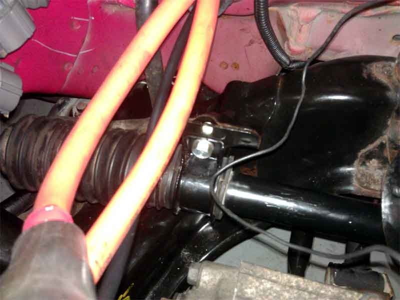
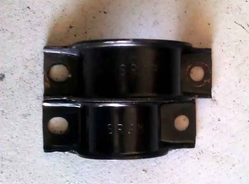
Notice the larger power steering bracket on top.
The
batteries are taking 40.9-41AMPS to recharge after the JLD404 meter
indicated 40.5AMPS. That is within the margin of error and I am happy
to see the batterys are consistant.
I talked with EVWest today and after I told them the clutch pedal had always felt like it had a very late release at the top of the pedal they would like to have the transmission/motor/clutch/flywheel to measure again. I am not going to go as far as pull the transmission but I will bring everything else down there next week. Uggh! I guess I can remove the battery box and coat it while they inspect the parts.
Posted: Tue Nov 27th, 2012 02:56 pm
One
more thing I took away from the conversation I had with Matt at EVWest.
This would be caused by the adapter hub being to long, not to short
like I had thought. So IF that is the problem, its much easier to
remove material then TO add it!
I also ordered a JLD7100 temp meter for the motor from lightobject.com . That should compliment the JLD404 nicely.
Posted: Wed Nov 28th, 2012 03:33 pm
Going
over battery arrangement in my head. I feel certain the best way to do
the strut tower battery box is a arrangement of 11 batterys stacked on
top of each other going between the strut towers. This willl leave me a
reasonable amount of space to work on the car with the battery box in
place. I tried arranging 4 batterys wide and 3 deep but that ran into
clearence issues with the 12v batttery tray, the brake master cylinder
and the transmission housing. So I lose 1 battery doing it this way but
I feel better about it long term. I am going to give the specs to the
shop on Monday and hope to have it within a week. Even though the car
will be likely apart come Monday with me taking parts to EVwest to
measure.
As far as battery box mounting I
think I want to try my hand at aluminum angle iron! Wow, what a treat!
It's the little things in life.....
It needs to support 85lbs of batterys.
Posted: Sat Dec 1st, 2012 11:17 am
Fun....
With
the batterys charged and time to spare I put 20 miles on the car just
driving around. I went to STARBUCKS and parked right up front and
popped the hood before going in to get an iced coffee. Not a lot of
people stopped. But a few did and I answered a couple of questions. On
the way home I decided to stop by Cinnamon Productions which is a
coffee shop/breakfast shop. Again I popped the hood and went inside to
get a bagel. When I got back out a crowd of 8-10 people where looking
over the car! The STARBUCKS crowd just grabs something and leaves. This
crowd sits down and has a meal. They can afford to spend a little time
to see something that interests them.
This
time driving the car the clutch barely slipped. I think I can attribute
this to learning how to drive the car. Meaning choosing the right gear
rather then lugging the car in a higher gear, no rapid acceleration,
let off the accelerator pedal a half second before depressing the
clutch to change gears, throttle slew rate of 200 in the controller,
etc. So EVwest is not totally horrible! Kidding, good guys!
Excited
about not having to remove the motor. To celebrate I decided to remove
the battery box behind the seats and file the holes down so the cable
terminals fit perfectly flat. I still am unable to find the room to put
the nut on the inside of the box. Dont know what to do about that. If
the cable terminal just had a deeper dish it would have worked out
perfect. As it stands not the terminals are very flat.
Oh
yeah it rained today. And I thought it was a perfect time to put the
Del Sol in the driveway and wash under the car. It looks really good,
better then the top half of the car at this point.
So
I removed about 64.3amps from the pack on this trip. I am charging the
first cell now to see how far the count it off. 65Amp Hours is my
target depth of discharge going forward. I figure this gives me
excellent pack life based on CALB's expected cycle life going from 80%
depth of discharge to 70%.
Monday I submit
the second battery box measurements. I also had the motor temp
controller arrive and I still need to line the box with bedliner. Maybe
the best thing to do is wait for the other battery box to be made so I
can coat them both at the same time.
The alligator clips that shipped with the Powerlab8 battery workshop have failed. They started to come apart. A quick visit to Radio Shack sourced larger and better quality clamps. I left a long lead of exposed wire and soldered it on the clamp in addition to bending the metal over on the clamps. I really recommend this to everyone. Come to find out from the manufacture that these clamps are something that EVTV provided to "complete" the kit. Not included from the maker of the Powerlab8.
Posted: Sun Dec 2nd, 2012 11:57 am
Oh how quickly things change.
While
perusing the internet for unrelated car items I stumbled upon a website
that offered a "Civic power brake delete kit"! This replaces the OEM
brake booster with a plate that can take a Wilwood aftermarket master
cylinder. At that point you just bolt the new plate and master cylinder
where your original equipment went and retap the OEM pushrod and your
all set. I do have to run brake lines to the junction valve on the
firewall.
In doing so I can put 4 rows of
batteries 4 wide when also removing the electric vacuum pump I already
had mounted and wired up. At that point I can reuse the wiring and use
it for the coolant pump (when I figure that one out). I would move the
signal wire for the relay from the brake signal on the soliton
controller to the 12v+ wire that the controller gets power from from a
keyed input.
OK so going from 11 battery's
all in a row to 16 batteries is hardly worth the effort but I like the
battery placement right over the wheels (hello understeer). Then after
looking at the battery arrangement on a table I lined them up the 11 I
had before but because of the new found room if I mess with the brakes,
I put them 2 wide. This totals 22 batteries and would be awesome if I
could pull it off. It would require trimming or removal of the 12v
battery tray and either relocating the battery or going to a smaller
motorcycle style battery. I was avoiding this before due to the 15amps
the brake pump used, but now with that removed its just the controller
and lights.
At that point it would be only
12 batteries left which I think I can locate where the gas tank was,
worse case scenario in the trunk area down low. But I would be @ 147v
for the tme being which is pretty respectable, IMHO.
So the mind is active and trying to find out a reason why this wouldn't be the best solution at this point.
Posted: Mon Dec 3rd, 2012 03:38 pm
I
tear my hair out trying to determine the best battery arrangement under
the hood! If I was'nt so concerned with getting a box made that did'nt
clear the hood I could have very easily got the 22 I was shooting for.
Sadly this has been narrowed down to a lowly 14. The 11 I had planned
before, stacked on top of each other going sideways and 3 going wide
sideways in front of them. And I am not going to mess with the 12v
battery placement for the time being (meaning until I can't find
anymore room and am forced to).
Underhood battery box will be:
26 1/4 long x
8 1/8 wide x
10 1/2 deep
I
could get 3 more batterys in this arrangement if the 12v battery was
moved. But with the concern for width space between the firewall and
the transmission, relocation was only an option when I could have put 2
rows of 11 batterys. And with 11 inches in width this 8 1/8 inches
makes all the difference!
Now the short term voltage target is 121.6
I
also trimmed up the speaker plastic behind the seats. I took the
speaker grills out then cut around them. When I was done I put the
speaker grills back in and it maintained a cleaner look.
A couple of pictures. First is the gland nut coming so close to the battery I can't get the nut on.
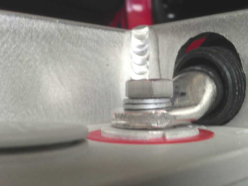
Secondly
is a picture of the cut grills and box placement. I still have to drill
1 hole in the grill to route a battery cable. It's to tight of a radius
to bend the cable on the outside of that trim piece.
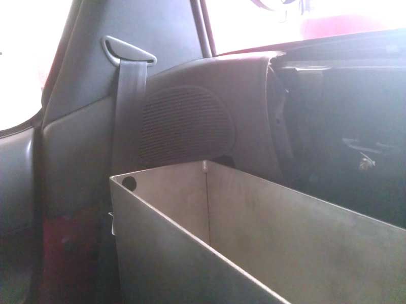
Posted: Tue Dec 4th, 2012 10:18 am
The new master cylinder is coming tomorrow, hopefully the adapter plate is not to far behind. In anticipation of that I removed the OEM Honda booster and master cylinder.
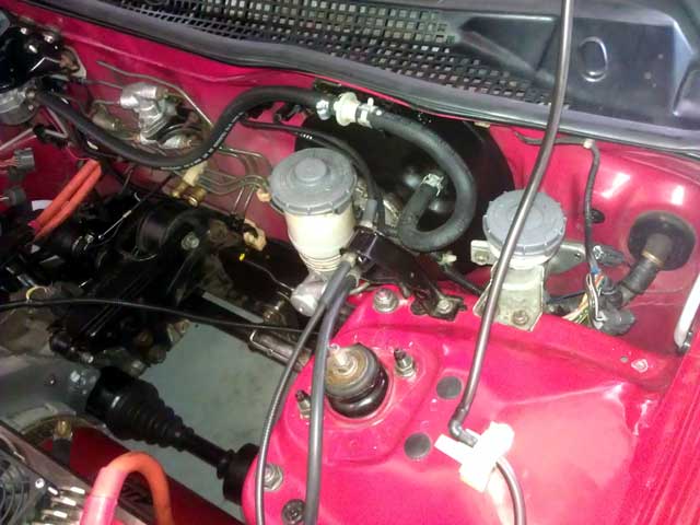
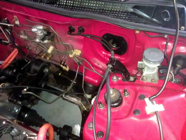
Posted: Thu Dec 6th, 2012 01:53 pm
TOOL RESET!
Have
you ever gotten to the point that your once clean and arranged garage
is now a mess and you cannot find the right tool? That day for me was
today. I rearranged the garage the first time in 9 years. In doing so I
ended up with more free space and the ability to open all the tool
cabinet drawers without hitting something. Of course there was more to
this event then is being told....more on that at a later date. But for
the moment everything is back to where it is easily accessable.
Still waiting for the plate to mount the new master cylinder. Also waiting for the battery box to be completed. And once I get the engine hoist moved back over to my house, I am going to pull the damn motor and be absolutely sure there isn't something wrong with the clutch actuation. Joyous!
Posted: Fri Dec 7th, 2012 03:30 pm
The master cylinder arrived yesterday and I was able to mock up the installation. This way I could order the brake line and fittings, which I did today and oddly enough cost more then the master cylinder! I hate fabricating crucial items like brake lines but I had no choice. I could'nt find any pre-fabricated lines with the fittings I want shorter then 18".
Posted: Tue Dec 11th, 2012 03:57 pm
I have the master cylinder mounted and am drawing up plans of routing the hoses. This may change but here is what I came up with so far.
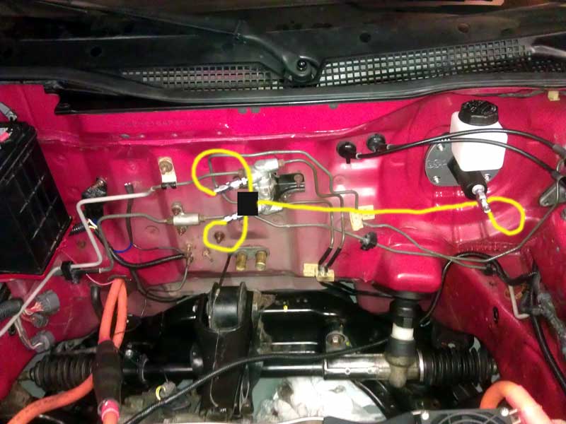
I
initially did not want to do a 90degree bend right outside the master
cylinder because of hindered fluid flow. But having it go out 3-4inches
ruins the point of going to this setup. So I ordered a 90degree bend
and hope to reduce the hose path. Along with that I had to order
another pushrod for the master cylinder. I hacked off 3/4inch to match
the OEM master cylinder throw. However in doing so I failed to take
into account the reduced depth of no brake booster. When I hooked it up
today the pedal was alot closer to the floorboard and the brake light
stayed on because the pedal was pulled away from its stop. That 3/4inch
is the exact space I needed. $8.00 mistake on my part.
Yes I know I still have the motor to pull but I wanted to work on something different!
Posted: Wed Dec 12th, 2012 03:37 pm
I
pulled the motor/flywheel/clutch from the car and am trying to arrange
a time to visit EVWest. I had told them Friday but I removed it sooner
then planned.
Summit is delivering the new master cylinder pushrod tomorrow
along with a 90degree angle fitting.
I should probably call about the other battery box and check its status tomorrow.
Posted: Thu Dec 13th, 2012 02:43 pm
I
heard back from EVWest this morning saying "Today was as good as any"
for coming down with the parts. I got down there and following a short
wait for Matt who was on the phone he and Michael got right to work
removing the clutch and flywheel. As soon as the clutch was removed it
was apparent something was wrong. Little metal filings where
everywhere. He kept looking at it and came to the conclusion is was a
clutch/flywheel issue. Maybe the wrong one or something. I told him I
double checked the part numbers and he was kind of at a loss. I then
told him look it was even hitting the bolts on the flywheel. BINGO!
Looking at the flywheel from the side you can see even without a
straight edge ruler that the bolt heads are sticking out past the
mating surface on the flywheel. Now what? Things where looking like I
would have to resort to the OEM flywheel bolts which I wasn't to fond
of. These bolts where stronger and expensive. Michael had the idea of
counter boring the hole 1/8" in depth for that extra space. I loved
that idea so that's what he did. The whole thing was time consuming as
he had to line up each hole with the drill press with a smaller bit to
find center on the hole, then lower the table crank and replace the bit
with the one that bores the whole bigger. Everything was done and I was
charged what I consider to be a very minimal labor charge to do the
work! They really stepped up to the plate today and I thank them for
the hard work.
So glad I pulled the motor
because if I had applied full pack voltage or driven the car for any
longer I could have damaged the flywheel and clutch. As it stands right
now the flywheel does have a couple lines in it, but those are only on
the surface as I cannot feel any depth to the grooves. Same thing with
the clutch, looks to only have been making contact with a small amount
of the surface area. The flywheel bolts where actually hitting the
rivits on the firction plate near the center. EVwest was also in
agreement, they would run the parts on their car. Whew!
That makes 2 things in recent days that I paid labor for using
a drill press, hmm.
On
my way home I stopped by the fabrication shop about my other battery
box. They are so busy that they haven't done it yet. At least they gave
me a quote on the materials cut to exact fit, $90.00. Then whatever
they charge for the labor to assemble it.
Then to the Honda dealer to get the parts I had ordered, no
problems there.
My Summit racing order showed up with the angle fitting for
the master cylinder, I like it ALOT better!
Sadly the master cylinder pushrod came the exact length I had
cut mine down to! So I have to lookup what went wrong there.
I came home and put the parts back on the motor. The motor is
under the car ready to be pulled up and put back in.
The bolts hitting:
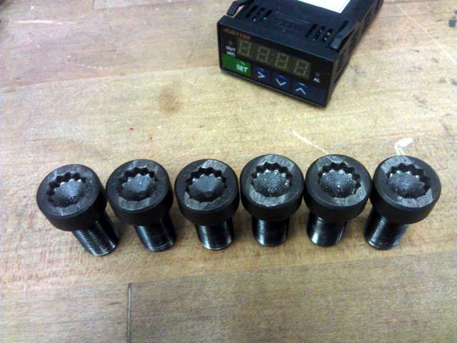
The flywheel modified:
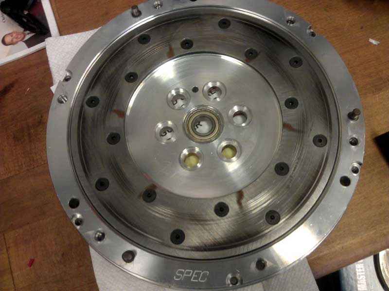
The minor wear on the clutch:
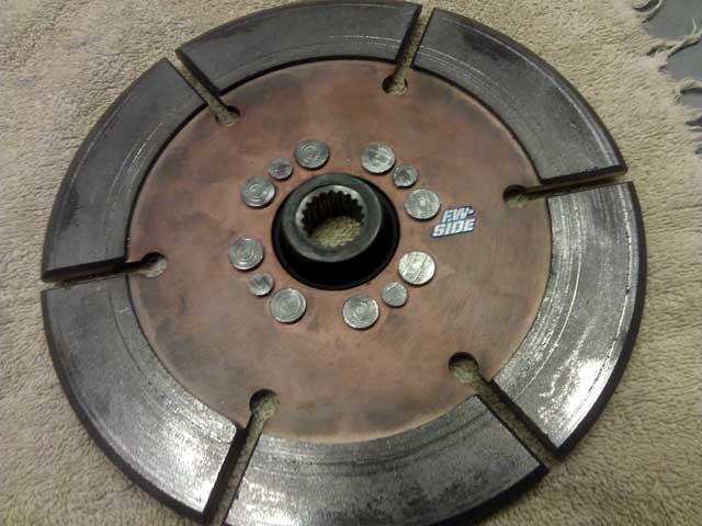
The revised master cylinder fitting:
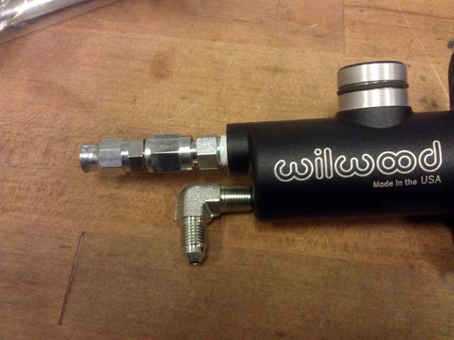
Posted: Fri Dec 14th, 2012 07:29 am
I could'nt wait so I put the motor in last night. There is
still wires to connect and a controller to mount, but its all there.
I got the master cylinder pushrod situation figured out.
Though it will be Tuesday until they recieve the part to ship.
Other
then that I want to paint the steel motor mount that attaches to the
endbell. This being the only bare steel part I have, its starting to
oxidize and look dismal.
One thing I would
have done differently and may still go back and correct at a later date
is replace and steel parts I fabricated with aluminum parts that is
hard anodized black.
I put the new angle
fitting on the master cylinder and as luck found have it, it stopped,
pointing to the passenger side of the car to the other fittings.
Upon reflection its probably a good thing that I am awaiting crucial elements of the brake system. As I can TOTALLY see me getting impatient and putting the battery box and 24cells back in the car to test the clutch and turn the slew rate back up a notch!
Posted: Fri Dec 14th, 2012 11:38 am
LOL
I can't make this stuff up! That manual steering rack I got off Ebay is
grinding when I turn it full left. It only happens in the last few
inches of travel before the stop.
I had'nt
noticed it before but since I had both wheels off the ground I moved it
from full lock to full lock to see if maybe it needed greased.
The
seller on Ebay has been great and is actually a California native
living back East. After talking to him on the phone he is going to try
and arrange something with a shop 130miles away in Palm Springs. I have
a friend out there so that may work out. I will know more tomorrow.
I removed any surface oxidation from the engine mount and if it does'nt rain all day tomorrow I will paint it.
Posted: Sat Dec 15th, 2012 01:37 pm
It
looks as if a rebuilt steering rack may be offered to me by the seller
at a greatly reduced price. And I can pick it up. I will know more
Monday.
The brake lines are giving me issue.
The biggest being the braided lines are hard to asssemble with no
specific tools. They also stick out to far from the firewall for my
taste.
I am going to do what I should have
done in the first place which is use the OEM lines on the firewall then
bend the lines ever so slightly at the endpoint to fit into a T
junction. Thankfully I did'nt manhandle the OEM lines like a enraged
ape (as is often the case) and I was able to use them with ease. And
the same place I am getting the T fitting from will custon make me a
braided line, any length. I will get this done Monday.
1 more coat of black paint on the endbell motor mount and I will assemble that.
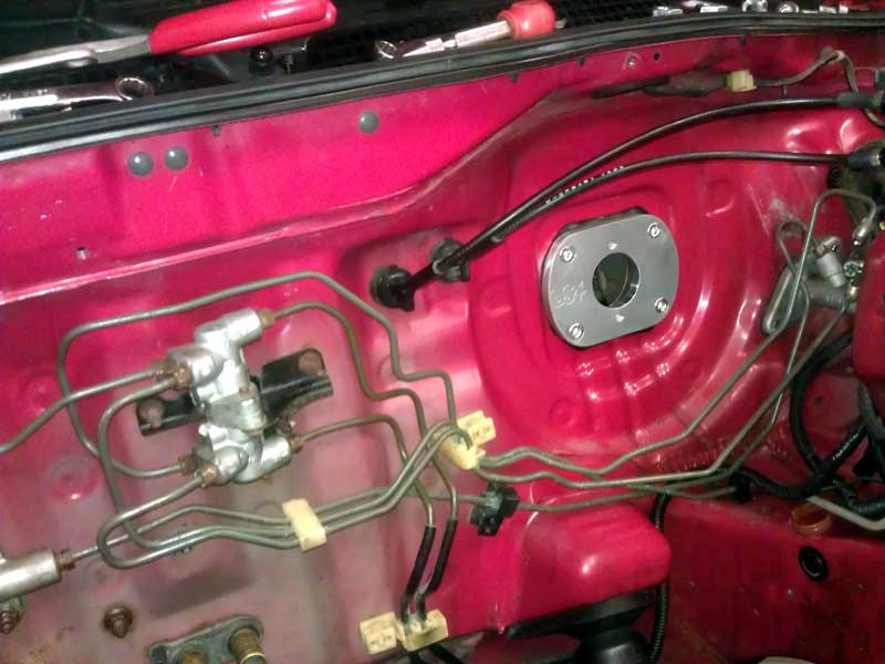
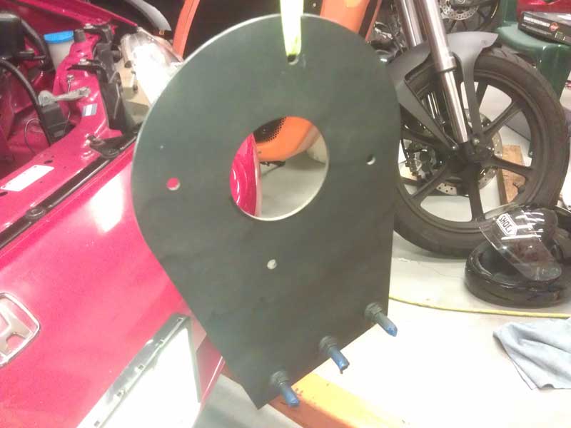
Posted: Mon Dec 17th, 2012 07:41 am
I
went to get a 18'' braided line and T. What I came home with was
$150.00 worth of fittings and lines! The shop worker explained to me in
detail that I COULD just put banjo bolts off the fittings on the
firewall and run braided line the whole way. I thought I would give it
a try.
However in the end I resorted to the original idea of a single 18" braided line and brass T fitting into the OEM hard lines. Sometimes the simplest choice is best. I am glad I know I have that other hose option in the future, should I need it.

The ETA on the master cylinder pushrod got pushed back a day from Summit racing. And I am also waiting for word on what my options are with the steering rack.
Posted: Mon Dec 17th, 2012 04:15 pm
OK I am happy with this fitment!
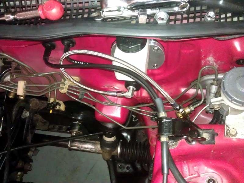
Posted: Tue Dec 18th, 2012 01:43 pm
Looks like I will be getting a rebuilt steering rack. Just
working on the details of payment with the original Ebay seller.
For
the time being until the rear battery box situation is completed, I am
going to charge off 120v with the charger placed under the hood. This
is so I can bottom balance the entire pack and charge it as 1 complete
string.
And this project is far from complete even though the car will
be much more useable.
What's left? Well lets see here....
New
motor mount made from 1/4" aluminum rather then 1/8" steel. This will
be a larger mount to accommodate the A/C compressor and associated
tensioner/idler pulleys.
Convert the A/C from R12 to R134a. This consists of new
O-rings and I think a new accumulator.
Build rear battery box.
Relocate charger to trunk.
Coat the battery boxes.
Run coolant pump to Soliton1 controller.
Add forced air cooling to Netgain Warp9 motor.
Figure
out if the heat from the controller will be enough to route through the
cars heater core or if I should figure out how to mount a PFC style
ceramic heater element inside the heater box in the car.
Install Civic HX wheels with low rolling resistance tires.
Streamline aerodynamics with sheets of plastic under the car.
(optional) replace all steel angle iron with slightly thicker
aluminum angle that is anodized black.
I can see this project continuing for a while. When I put the motor in just recently I found a better way of routing low voltage (12v) electrical wires that I had'nt noticed before.
Posted: Sat Dec 22nd, 2012 01:15 pm
Still no word from the seller of the steering rack, so I am stuck waiting. But that does'nt mean I stopped doing "stuff". Santa brought a tool I have been always wanting, but never set out to buy one. And installing it correctly meant drilling holes in concrete and going through 3 different type of fasteners until I found one that I liked.
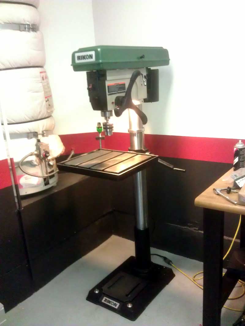
Its a new RIKON 20" drill press. Funny as I have done most of the metal drilling on this project already!
Posted: Tue Dec 25th, 2012 01:21 pm
I did some time filler stuff today. I began filling the master cylinder with brake fluid and pumped the brakes. A little dribble of fluid came out and I tracked it down to the T fitting that had the hard lines. The nut indeed bottomed out in the T fitting but it needed to be deeper. I was able to move the fitting around slightly with the hardline tightened down. And if I could barely do it by hand, it would be nothing to 1000+PSI of pressure. Luckily I hadn't returned the braided line yet and ended up using most of the parts. The line looks tight in the picture but there is some free play.
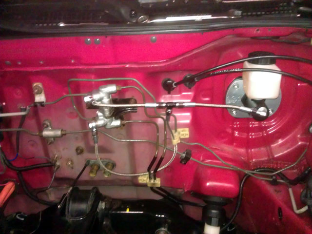
I also started preparing the charger for the 58 cells to charge as 1 string. Of the 10 charging profiles loaded into the charger I had them load profiles for 53-62 cell counts. I can play with that range to get the charge voltage I want. The profile that was activated was a charge to 208.8v or 3.6v per cell. I decided on a 205.2 charge voltage which equates to 3.53v per cell. It was that or 3.47v per cell. Hoping that decision doesn't come back to haunt me.
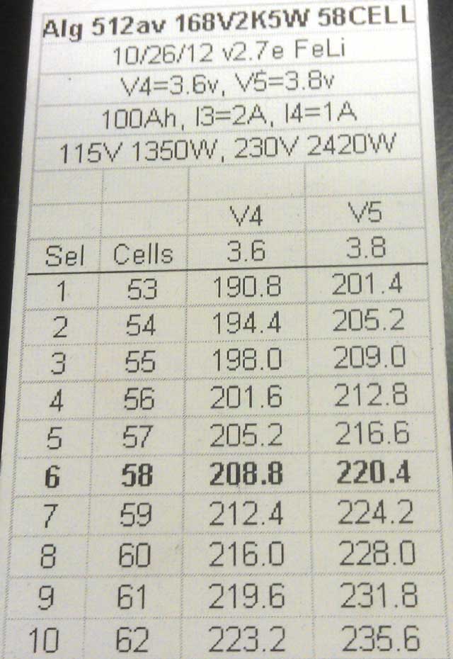
I
also used the drill press for the first time last night. I drilled a
hole in the right rear speaker grill for a battery cable to go through.
This was king of a tricky cut because very close to it had a clip mount
for that piece to go into the sheet metal in the car to secure it.
Having a precision way of stopping the downward drilling I was able to
complete that in epic fashion.
My guess is the front battery box should be complete this week (if they are open).
Posted: Thu Dec 27th, 2012 11:23 am
I had one cable made from EVWest and I have to go back tomorrow because they are out of gland nuts for the other cable! ERR! I stopped by the fabrication shop on the way home and they are closed until the New Year. So with 1 cable complete and the prospect of waiting a week I may just get impatient and...
Posted: Thu Dec 27th, 2012 01:55 pm
Good deal, the seller of the steering rackissued a partial refund so that I can use this rack as a core. And as luck would have it I found another one that is rebuilt from a LOCAL place on Ebay. I will try and arrange shipping to a local auto shop (free) or just go pick it up in person.
Posted: Fri Dec 28th, 2012 03:53 pm
I seriously need to put down the tools! I have found another revision to be made on the brakes. I have officially hidden my 10 and 11mm wrenches to prevent me from revising it further.
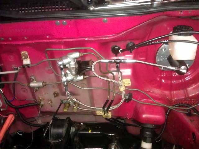
I
went to EVWest today and they finished crimping the remaining battery
cable. I then convinced/conned them into building me a cable for the
Elcon battery charger with ringloop terminal ends.
I
have been in contact with a follower of this webpage that advised me of
a questionable charging algorhythem on the charger in that picture I
posted earlier. I have call's into a couple people on this.
Looks like I will pull the steering rack Sunday night and them
go up and get the rebuilt rack on Monday.
I threw the battery box back into the car and have everything wired up, just need to bleed the brakes at the brake caliper to drive it around with 144v and no slipping clutch!
Posted: Sat Dec 29th, 2012 07:09 am
Put
the car together and drove it about 15 miles. Sadly the clutch is still
slipping. I will call EVwest next week but I guess this means pulling
the motor and transmission and bringing both to them.
I
was also able to test the car in the rain! I had'nt planned it that way
but 6 miles from home is started raining and by the time I got home it
was pouring.
Pretty dismal day but I will find something to make better or route differently this time around. Driving the car cheers me right up though! I took it by a gas station I always stop and get energy drinks at. Not sure if they thought I was joking about this project but they all came out to look at the car and that was awesome.
Posted: Sun Dec 30th, 2012 08:09 am
Someone
does'nt want me driving this car! After yesterdays rain, I set off
today to the local STARBUCKS. I got my iced coffee and saw dark clouds
in the sky so I decided to head home. Not even time to talk to anyone.
I did'nt even get out of the parking lot before HAIL started coming
down and continued the whole way home! I made it home and everything
was fine but that ended todays car festivities.
Before that happened I did do some very unscientific testing. After a few miles of neighborhood driving I pulled over and measured the front tire temps with an infrared thermometer. The drivers side front tire was 15F hotter then the passenger side with eqaul tire pressure. That pretty much confirms the car is out of alignment, nothing new there.
Posted: Wed Jan 2nd, 2013 08:48 am
Going
to get a remanufactured steering rack tomorrow. Using the old power
steering rack as a core. This way I can play with this old manual rack
at a later date with some different ratios from a company I found that
makes them.
I have also been in contact with SPEC clutches that want to know the production numbers off the clutch disc. I am hoping the reason they want to know the numbers is not to verify the application but that there was some sort of a recall. I can't be THAT lucky! I will have to remove everything again anyhow so I will know after I get the new steering rack in.
Posted: Fri Jan 4th, 2013 02:12 pm
I got a rebuilt steering rack and installed it. I had to order new tie rod boots from Honda but initial feelings are a much improved rack. Got the hoist moved over to my house and the motor pulled today. I just got done and don't see any obvious problems, other then being glazed but I will look more tomorrow. I did not see the 4 digit number I am supposed to verify with SPEC but I will look again.
Posted: Sat Jan 5th, 2013 12:31 pm
Should
I? I looked over everything today and the only thing I could see as an
issue is the glazed clutch plate. I don't even use the clutch for the
most part! So the only way I see that this happened is when the
flywheel bolt heads where rubbing and preventing full engagement.
With
that idea I set off to clean up the existing parts. I milled down the
clutch friiction plate with the drill press. I put a new firm brush in
the drill. Then I puled the drill head down and set the stop for a
tenth below where is started to touch. I then degreased the clutch
friction plate and metal disc. After that I heated up the items with a
heat gun before the drill press. It was time consuming verifying
everything was level, bringing the brush head down, repositioning the
parts, and repeat. The only thing I did'nt do was remove the flywheel.
I felt degreasing it and using a wire brush on a handhend drill wsas
good enough. That may come back to bit me. Which is ok. I did this to
avoid the $80.00 SPEC wants for a new flywheel surface. If this ends up
being an issue iin the future I will just get the part.
I am so confident on how things are right now I am debating just to put everything back together right now! Not even waiting for the e-mail back from SPEC to help me locate the number they wanted!
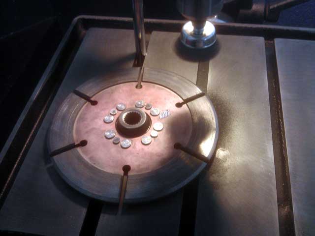
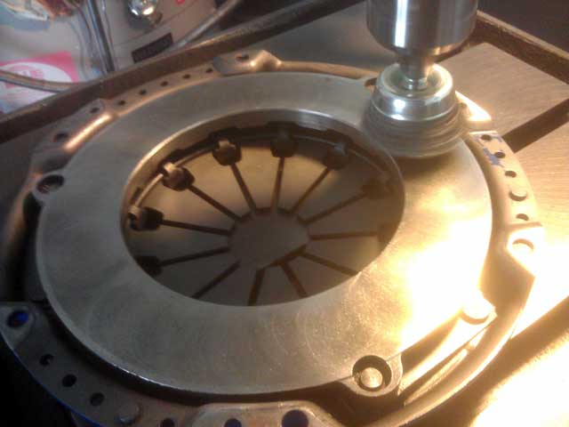
Posted: Sat Jan 5th, 2013 06:33 pm
Car is back together. I will give it a try tomorrow. I do better with disapointment after a good nights sleep!
Posted: Sun Jan 6th, 2013 11:22 am
I took the car for a test drive today. It still slips. Alot less then before, but its still there. This after I got an e-mail from SPEC directing me where to look for the numbers. Ahh well!
Posted: Mon Jan 7th, 2013 04:15 pm
I
took the time do do a more precise wheel alignment (still by eye at
this point). I also put the new tie rod boots on and torqued everything
down.
So its a toss up of what to do. I can
derate the maximum power and tone done the slew rate in the controller
and try and slowly increase things as time goes by. Or I can yank
everything and order a new flywheel friction surface and look for that
mystery number on the clutch. I know what I SHOULD do but I am inclined
to mount the batteries I have, charge the car, and go out on the road.
I called on the underhood battery box today and was given a
"couple of days" timeframe.
And I have been busy with other things that I have'nt sent off the battery straps to exchange for smaller ones.
Posted: Tue Jan 8th, 2013 04:42 pm
I decided not to tempt fate and wait for the right size
battery straps to come in along with the underhood battery box.
The consistant 3.28v I was getting with 70% D.O.D. has now gone to 3.21-3.25v at 80% D.O.D. and I think it will only by more spread out as the capacity gets lower. I now realize the full value of balancing the pack at the bottom.
Posted: Thu Jan 10th, 2013 10:43 am
All the battery that where in the car are now out on the floor
of the garage. They are ready for bottom balancing.
Jack
Rickard from EVTV was nice enough to send out the different battery
straps I needed before receiving the other ones back! I really
appreciate that.
The under hood battery box. Ahh yes the battery box. Well that is not going to be done until next week at the earliest. I will reserve judgment until I get the box and see what the bill is!
Posted: Thu Jan 17th, 2013 12:08 pm
The
straps came from EVTV and I assembled them as a pack for the first
time. I have begun the slow and tedious process of bottom balancing
before charging them as 1 complete string.
The
underhood box is still not done. Blaming the flu and everything else
under the son I got a commitment to have it completed tomorrow.
I am going to put this box in the trunk for now until I am convinced the clutch won't become an issue. I may start making the shelf for the box anyhow.
Posted: Fri Jan 18th, 2013 04:48 pm
I
still don't have a battery box! UGG I dispise this fabrication shop.
The way I ended it yesterday was they did'nt even have the material.
Then I get a call back saying it was in between some other material
they had already recieved. So I went ahead and told them to make it.
Then he calls back saying the material was a bare sheet and not cut. So
he said he would reorder the new material already cut and assemble it
today. I can't believe the hardest part of this project it creating 1
battery box. Of course it does'nt help that this is one of the
finishing items to the project.
So maybe Monday? I suppose.
I
am on battery #12 on the initial battery drain for the bottom
balancing. I remember Jack Rickard saying with a 12v battery you could
do regenerative discharging for a long time and it would never
overcharge the battery. That may be true but something happens that you
don't want. The initial discharge is to 2.5v @ 30amps. Understand that
is not the true voltage. After 24hrs the battery bounces up to
2.8-2-9v. You then discharge to 2.65v and from there you either add or
remove the from there. Problem is when you do get the 12v battery
charged to about 14.5-14.6v the regenerative current tapers off to
about 10amps. When it does that it is possible (in my eyes) to
discharge the cell to 2.5v under the 2.75v rating for empty. See you
are counting on that 30amp surge to "spike" the discharge curve and
then recover. When you discharge at the more gradual 10amps there is no
"spike". I am also draining to 2.75v and not 2.5v. Don't know if I am
explaining it correctly. To be sure the battery never overdischarges I
have added a small 23w 12v bulb to the battery to drain off excess
voltage. And also at the end of the discharge cycle I leave the bulb on
to dip the 12v battery voltage down lower so it can never get to 14.5v.
(Maybe it would on a full discharge of the cell but not the 25AH I am
pulling from each of these cells.
And I am not draining each battery to the 2.75v on the first pass. Because its my opinion that you want to leave the batterys at 2.75v for the shortest time piossible. It will take longer to get to a true 2.75v but I think this is a more failsafe way of doing it.
Posted: Mon Jan 21st, 2013 12:10 pm
Good
news, I have the underhood battery box! The parts where $90.00 plus 2
hours labor at the same rate. I am happy with the part, just wish I
did'nt have to go through this much trouble. The lady at the shop who
wrote up the bill said $135.00 for the metal plus 2 hours labor but
when I questioned it, the materials where quickly revised to $90.00.
When I asked why there was a discrection in the amount she said she
wrote them down wrong. SHADEY INDEED!
I am on battery #36 of the botom balancing procedure. My hopes are finishing that up tomorrow and charging it for the first time. Thoughts are running through my mind of setting up a sleeping bag in the garage in case something goes awry in the process.
Posted: Wed Jan 23rd, 2013 09:41 am
Still bottom balancing! Not enough hours in the day lately. More to come..
Posted: Thu Jan 24th, 2013 04:16 pm
The initial drain of the cells is done. Now to wait 24hrs and
then trim any last remaining voltage to achieve 2.75v per cell.
As
it turns out even bleeding at a low amperage will still recover at the
same rate as faster discharge. I had initially started to drain the
cells to 2.60v to be safe but I had to trim to much after they
recovered over 24hrs. I now drain them to 2.5v regardless of amperage
of discharge.
Looks like I may have timed it right. With overcast days ahead I will wait until off peak hours this weekend to expend 19-20KWH to charge the cells.
Posted: Fri Jan 25th, 2013 03:30 pm
16 cells completed. I hope to finish it up tomorrow.
Posted: Sun Jan 27th, 2013 01:09 pm
Would you believe I am still bottom balancing? Yes it's a case of OCD but I am bound determined to match each cell within a thousandth. It's all pointless I know but where there is a will...... Looks like I wont begin the rexharge until at least this time tomorrow. I found a couple of cells I had charged to 3,25v and they need 24hrs after discharge to a steady voltage.
Posted: Mon Jan 28th, 2013 01:09 pm
OK
I need to officially put the tools down for a moment! Why I have set
this as a personal mission to bottom balance so closely beyond me. The
thing is .010-.020v on thw bottom end willl likely be less then .001 at
the top end of the charge. So I guess I will have to "settle" for
individual cell values of 2.750-2.756v. And if it was'nt for waiting
24hrs for the cells to finally settle out from today's trim, I would
charge tonight.
I will go over the pack again tomorrow morning and then at 6pm when the electric meter switches to "off peak" billing, I will begin the charge!
Posted: Tue Jan 29th, 2013 01:12 pm
Charging has begun! Don't know how long I will let it run tonight. The pack voltage on the drained pack was 160.3v
Posted: Wed Jan 30th, 2013 09:23 am
8 1/2 hours into the first charge. I broke it down into 2 segments so far. I plan to finalize the charge tonight. As the batteries get charged the minor differences between them have gone away. Now they are even closer together. I can imagine at the top of the charge the batteries will all measure the same.
Posted: Thu Jan 31st, 2013 01:16 pm
Charging took a time out, but its back on.
I
had taken measurements of cell votage from all cells during the
recharge process. When the charger reached 85% charged I decided to
take another measurement. All where ok with voltage between 3.33-3.34
each cell. However one cell measured high! I stopped charging and took
that out of the pack. I then reconfigured the charger for a lower
voltage and have begun the final charge. This throws a wrench in the
bottom balancing scenario as I now have to take all cells down to 2.75v
again to introduce this new cell into the pack. I e-mailed Jack Richard
to see what ideas he may have and what can be done about this cell.
Other
then that I am drilling holes in the underhood battery box and
reconfiguring the arragement so I have bother battery cable coming out
the same side right next to each other. This is awesome, and luckily
the shop that made the box where not spot on with the box. I am
stacking the batterys one on top of each other on the top row, then a
final row going sideways on the bottom. It looks great!
Tomorrow I am going to try and coat the boxes in primer to get ready for the bedliner coating.
Posted: Sat Feb 2nd, 2013 04:52 pm
The boxes are primed and ready for coating. I will try and get that done Monday
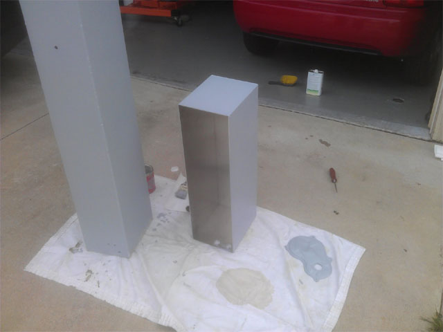
That
small little panel on the right is/was the fuel pump access panel. I
primed that because I want to fill the plug hole and coat the whole
thing to deaden roadnoise.
On the battery front here is what happened. I freaked out when I saw 4.0v on one of the battery cells during recharge. Then upon further inspection I found 3 other batterys that had readings of 3.7-3.8v. I then bled less then a tenth of an amp from the connected pack and the cell dropped to a more reasonable 3.34v. As luck would have it I have been in contact with a regular vistor to this website named Jon Rue who was reassuring and provided insight into this process. So much so I would love to post one of his more in depth e-mails here if permission is granted.
Posted: Sun Feb 3rd, 2013 04:51 pm
Here is one of many e-mails to be from Jon Rue,
First let me tell you getting the batteries setup right is probably the most difficult part of the whole conversion process. It seems like everyone either downplays it or doesn't fully appreciate how challenging and important it is. The good news is once you get it done right you pretty much have a battery pack that is maintenance free. Seriously after this you'll be enjoying your car for years without much worry about your batteries at all.
I suppose this is where the market for BMS systems is. It is tedious and yes the appeal of not doing the grunt work or not trusting yourself to get it done right and just relying on a BMS is compelling. I tell you though these people just don't know that all it takes it a one time setup and you're good to go.
Here is a sampling of the different end of charge cell behavior in my pack that might be useful for understanding what's going on with your cells near the end of a charge. I've seen a very similar chart from John Hardy in his battery testing. A couple of things to note. At time zero (about 45 minutes before charging ends) the cell voltages are all within about 0.02V from each other but some cells start diverging soon after that. Then the chaos that is the constant voltage phase begins. There are 4 distinct modes in the CV phase but understanding what's going on isn't that important to me other than to recognize that each cell is going to behave in its own way during this phase. What is important are your cell voltages at 2 points: at the end of the constant current phase and at the end of the constant voltage phase. These points are where you're going to find your extreme values so keep that in mind when you're monitoring charging.
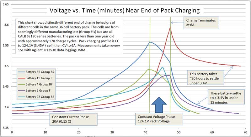
Like I sort of mentioned in a previous email a bottom balanced pack is the right point to start from but it doesn't guarantee your pack will be charge safe. Charge safe means different things to different people but for me a charge safe pack is one where no cell exceeds 3.65 volts at any point in the charging process. I for one believe a charge safe pack is more important than a bottom balanced pack and am willing to diverge from a pure bottom balance configuration (albeit as minimally as possible) to maintain a charge safe configuration. I suppose sometimes you can be lucky and bottom balancing alone can yield a charge safe pack but I think that is typically unlikely.
So in a sense it's not all that surprising you have one or more batteries spiking in voltage near the end of charge. I think it's quite normal though 4volts is concerning. I did have hopes that this would be minimal with the new CA series cells. I believe Jack is comfortable with cells going up to 3.8 maybe 3.9 volts during charging but you'd have to ask him. My comfort level isn't up that high. The other really important factor is using the right charging algorithm but we've already had that conversation.
-Jon
Posted: Mon Feb 4th, 2013 01:23 pm
Still
trying to find time to coat the boxes in bedliner. I did finish coating
the access panel door with bedliner but it went on pretty thin,
regardless of the 2-3 coats. I am glad to be using thicker liner on the
main boxes.
Imagine my surprise that within
the first minute of this weeks EVTV show my name was mentioned. This
was for razzing host Jack Rickard via e-mail on my observation
regarding the lack of reporting OEM EV news that I had seen the past
couple of weeks. Then he goes onto 46 minutes of reporting OEM news,
the most I can remember! Thats great Jack and I love your show.
I am not even going to think about batteries until these boxes are out of the way.
Posted: Tue Feb 5th, 2013 09:16 am
Crummy weather all day! Hoping to coat the boxes tomorrow.
I did remove 3 threads or about 3mm from the brake master cylinder pushrod. Now there is no worrys about it having pressure on the calipers, plenty of adjustment either way.
Posted: Wed Feb 6th, 2013 04:00 pm
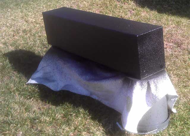
Both battery boxes are coated. I finished the first large one and then halfway through the smaller one I ran out and had to mix another bottle (kit includes 4). I ended up having about half a bottle left and with nothing handy to coat and the mixture getting ready to start setting I coated the boxes again and threw out the remainder. I should have had more things at the ready to coat but ol well. To speed the curing a little bit a lightly applied heat from a heat gun. That seemed to help enough to left me move the boxes back into the garage. A full cure is 24hrs and I am playing with the batteries trying to figure out if I really have a bad cell. Jack Rickard from EVTV says he will exchange the bad cell if it is found to be a problem. Nice to have that option, but I want to make sure.
Posted: Sat Feb 9th, 2013 02:06 pm
I coated the inside lip of both boxes with the thinner 3M spray on bedlinder. I coated down about 5 inches fron the top because the rest of the way will be covered up with batterys and I dont want to add any thickness to the box. I also made another false bottom to the smaller battery box so it brings the batterys up to the holes I drilled in the box. Everything is back together with the exception of the terminal straps on about 30 of the batterys. I will finish that up tomorrow morning and take it out for a drive. In the back of my head I am thinking the clutch will slip. At least the battery boxes look nice!
Posted: Sun Feb 10th, 2013 07:07 am
Delay of game. I need to swap out 4 more batterys straps for larger ones. At this point since I don't have a final configuration for the last large battery box, I may just buy 4 more without sending these ones back. I think iit is starting to look nice. The porche decking I have been using on the base would fit perfectly on top of the box as a ciover. I am just not inclinded to add another 13lbs to the car for a box lid!
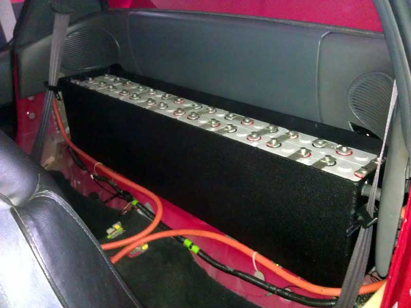
Posted: Tue Feb 12th, 2013 11:46 am
Rather
then wait to exchange the straps with EVTV, I drove down to EVWEST and
bought 4 battery straps. They don't match anything else and are solid
metal, but this is just for the time being anyhow.
On
the test drive if I give it heavy acceleration, the clutch still slips.
The car is still useable at this point. I am going out of state soon to
pickup my girlfriend for a month long visit. It would not be fair to
her to work on the car while she is visiting, so I guess that leaves me
idle for the moment.
Of course if this is like visits past, I will find time to sneak in the garage. But enough time to pull the motor? Not likely!
Posted: Fri Feb 15th, 2013 09:53 am
Put 47 miles on the car today, consuming 41 Amps! I think thats pretty good. This was all without some aerodynamic shrouds, 4 PSI low on the tires, and a car that has yet to be aligned. Hate to make it sound like excuses but I think there is good potential for a 90+ mile range car. Clutch slips if I am hard on the accelerator, so that is still an issue.
Posted: Fri Feb 15th, 2013 02:10 pm
Going to re-test things tomorrow. That energy usage is to good. I may have not reset the trip meter or something. Hmmm
Posted: Sat Feb 16th, 2013 01:21 pm
OK, back from fantasyland. I must have forgotten to reset the trip meter yesterday for the final run before recharging. Today I went exactly 20 miles and the battery back took 7KWH to recharge. Take out another 8% for charging losses and this equals out to 322 watt hours per mile.
Posted: Sun Feb 17th, 2013 05:14 pm
Alot of items are not in the permanent location on the car. And going with that theme instead of pulling in to charge and attaching the Anderson connector I have leading to the pack leads on the controller to the charger sitting on the floor of the garage, I am mounting the charger temporarly on the vehicle. This is so that I can hook up 220v and charge quicker. I had held this off because until I had a couple charge cycles under my belt I was'nt going to charge any quicker. Now that I am certain the charger is charging at the right level I can increase the charge output. So for the time being I am going to mount the charger on some plastic decking I have left over on top of the battery box that is in the trunk (the one that goes underhood eventually). I can then get some charger leads made up with the right size ring terminals and put them one on the + side of the pack behind the seats and the - side in the trunk. I still need to find a way of terminating the leads on the Elcon 2500 charger to allow 220v. Supposidly the 110v cord that ships on the Elcon handles 220v current so if that is the case I need to terminate the leads on the J1772 socket with a female socket.
Posted: Wed Feb 20th, 2013 06:59 am
I
had to buy a replacement 12v battery for the time being. I had left the
key on a few weeks ago and drained it totally down. I recharged it but
it was never the same. When going around the block the car started to
shut off and I quickly related this to me pressing the brakes and
putting a load on the battery. The battery was an 8 year old non
branded unit that I did'nt feel bad about replaceing.
For
the time being I also bought cheap coilovers sleeves and springs from
Ebay. This way I can get the ride height more level until I figure out
where the weight will be distributed. The kiit comes with front and
rear sleeves but I think I will only use the front for now, the back is
only lowered a little over factory.
Oh an I
may have found a way to get the motor out and check the clutch before
the girlfriend comes into town. This involves gettting cable TV for a
month. May be worth it!
Other then that I am still relocating the charger to the trunk and have the decking cut, coated with bedliner, and drilled. I even have all the nylon hardware to affix it. What I am having a hard time finding is a 220v rated recepticle the the NEVA style pinout of a standard 110v plug.
Posted: Fri Feb 22nd, 2013 12:53 pm
Doing freetime stuff that doesn't really apply to the conversion. Repainting windshield wiper arms and cosmetic stuff. I have driven the car around for 200 miles now and I do feel the motor has to come out to inspect the clutch but it is useable as a vehicle for the time being.
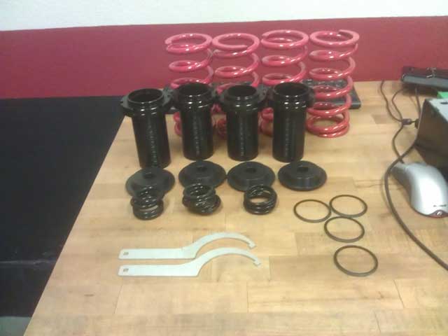
I recieved the coilovers I bought off Ebay. I am sure its the best CHINA could make (if thats reassuring). I am more inclined to set these us as "helper" springs to the OEM setup. However that does'nt help if your already to high to begin with. Until thoughts of snapped springs and fiery death are absent from my mind I will only use the front setup for now. I still can't believe it was $50.00 shipped.
Posted: Fri Feb 22nd, 2013 01:23 pm
OK, I already freaked myself out! Looking online for coilover install instructions I found a few posts that question the quality of the springs on these kits from CHINA sold on Ebay. Including a post that outlined someone's front wheel denting the fender and causing $700.00 in damage. So to reassure myself I ordered 2 quality, American made, 450lb springrate coilover springs from Summit racing for the front.
Posted: Sun Feb 24th, 2013 06:30 am
Today
I went back through the info I have logged. From the couple hundred
miles so far I have been getting between 325-345watt hour per mile. A
quick Google search reveals the general average for electric cars to be
200-400 watts per mile.
The good springs for the coilover sleeves are due here on Tuesday so I hope to get them in and the car finally aligned this week. A deal fell through on a Craiglist ad for some Honda Civic GX (Compressed Natual gas) wheels that would have been perfect. I am also looking into the first generation Honda Insight rims.
Posted: Mon Feb 25th, 2013 01:43 pm
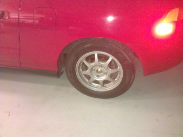
I came across a deal on Civic HX rims I could'nt pass up. I ended up trading the OEM wheels for the HX rims and half worn tires for $150.00! I think it was a good deal. The rims are not perfect and they have been repainted but they do look good. The OEM Del Sol "fat five" rims weigh 31.84lbs with tires. The Civic HX rims with tires weigh 27.28 for a 4.56lb weight saving per wheel. I will see how it drives tomorrow.
The coilover springs also come in tomorrow.
Posted: Tue Feb 26th, 2013 05:32 am
I drove the car for 15 miles this morning. I calculated out
313 watt hour per mile.
Because
these tires have more tread then the previous set I can really tell how
out of alignment the car is. Whenever going around a turn and I cross
over painted stripes on the pavement it makes an audible chirp of the
tires.
Can't wait to lower this front end and get it aligned!
Posted: Tue Feb 26th, 2013 01:26 pm
1
side is done. I grew tired and rather then mess something up I will
save it for tomorrow. I looked forever to try and locate the stock
Honda fender gap from ground to fender through the center of the wheel
cap. Would you believe its hard to find a unmodified Honda to take a
measurement? The measurement I had was 26 and 3/4inches which was very
high. I found 25inches to be a good looking height. I had to remove the
bump stop entirely which I was not happy about. And judging by the
amount of adjustment I could have gone an inch longer on the spring to
8inches. But since most people buying this kit will want to lower the
car it won't apply to them.
I can tell by
visual inspection alone these springs are higher quality then the ones
that came with the coilover sleeves. You can see the smooth shot peened
lines of the metal windings vs the grainy almost "cast" bumpy
structure. It just looks better made.
Some specs I took:
OEM strut and spring assembly: 11.75lbs
Aftermarket strut and spring assembly: 8.07lbs
Posted: Wed Feb 27th, 2013 11:02 am
Car is back together with coilover sleeves installed and drives GREAT! I think 450lb springrate was the right choice, that may change as I move weight to the front end. And the solution to that is use the 450lb springs for the rear and buy 550lb springs up front. The next thing is an alignment which I hope to do this week.
Posted: Thu Feb 28th, 2013 07:21 am
Rather
then take it in for a 4 wheel alignment I did a 2 wheel alignment
myself. I will eventually get it professionally done but until I have
everything where I want it to be, and the weight has been distributed,
I will hold off. I visually adjusted the car last night and I did
pretty good. Using a couple tape measures and a large angle ruler I
adjusted it the rest of the way. As suspected the car was "toe in" and
I did pretty good. The rear of the front wheels width was 65.75inches
and the front was 65.5inches. It was just dumb luck to have it within a
1/4 inch but I will take it! The car tracks strait as an arrow on the
road. The only thing left is I have to pull the steering universal
joint out and move it over 1 step on the teeth because the steering
wheel is a little off center.
I will get some usage data in the next couple of days to see if there is a measureable improvement
Posted: Fri Mar 1st, 2013 12:52 am
318watt
hour per mile is what I recorded. This is not an accurate measurement
however. During that 31mile trip I went far outside of my control loop
I use to test. With the weekend coming up I will have more time to
recreate the test.
EDIT, THEN RE-EDIT: BTW
that 318watt hour per mile number is at the wall after a recharge. So @
the pack that would have been 292watt hours per mile at the pack.
And I stumbled upon a alignment shop that would do a 4 wheel alignment for $69.95! Thats within reason.
Posted: Sat Mar 2nd, 2013 08:12 am
Another
16mile trek which used 318watt hours per mile. Then today at 8AM with
light traffic on a 20 mile commute I got 286watt hours per mile.
I put the interior more together to make it look presentable for the DMV inspection on March 13th. I mounted the JLD404 meter where the ashtray was in the center console for the time being. I need to cut some decking for a lid on the battery box behind the seats to complete the "look".
Posted: Sun Mar 3rd, 2013 03:29 pm
While
looking at the drivers side wheel from the front today it appeared the
camber was way off. What happened (I think) it by not having a constant
force on the spring when I went over a large bump, it upset the collar
on the perch at the top of the spring. This was only a matter of time.
So I did what I sdhould have done in the first place and order coilover
springs 2 inches longer (now 9) to put a constant force on the
assembly. There is no universal springrate and spring length for
coilovers. Because this was an application specific Ebay auction I had
hoped otherwise. I also increased the springrate to 550lb to prepare
for the added battery weight up front.
I am going to try and drive to National City (basically Mexico) this week to get some sheets of plastic for under the car.
Posted: Tue Mar 5th, 2013 03:42 pm
I recieved and installed the springs today. I will drive it
around tomorrow but I can already tell I need to lower it more.
Playing photo "catch-up".
JLD404 meter mounted in center console with interior back together:
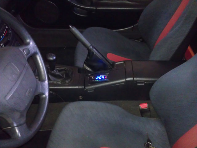
Metal stock I used to make into coilover perch mount collar:
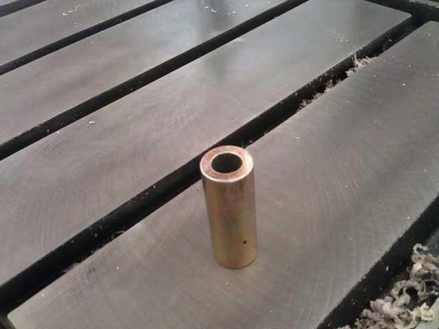
Mount modified, notice I had to drill the hole out and then put a metal file sideways to create ridges for a tighter fit as visable on the right:
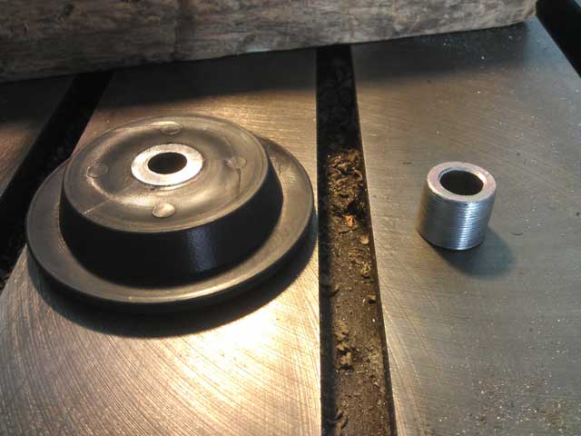
Posted: Wed Mar 6th, 2013 07:02 am
I
spun down the height adjustment all the way on the coilovers. It still
rides to high for my liking. Instead of trying to source some 8inch
springs (I found many) I will wait until the weight of the batterys is
moved up front. Other then that....I am going to get the 2 3/4x48x96"
sheets of black plastic tomorrow. I found a forum thread to give me
idea's @ http://ecomodder.com/forum/showthread.php/diy-removable-grill-block-1994-honda-del-sol-22488.html
but I think I will choose a different route.
The
nice thing is the company that sells the plastic can also cut it to
spec. So I already know I need one for the inside battery box lid. But
if the plastic looks strong enough I will have them make 2 and replace
the heavy porch decking I already have as a base.
More pictures:
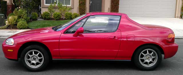
Room for batterys:
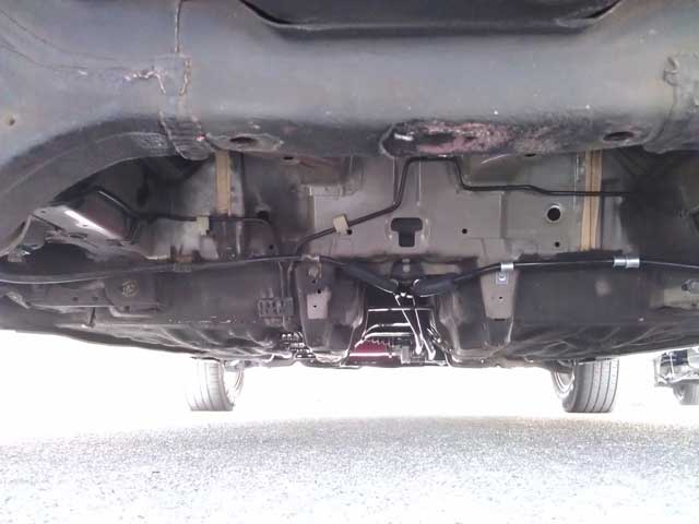
Posted: Wed Mar 6th, 2013 12:52 pm
Not
sure if this falls under the Brammo or the Del Sol thread. @ STARBUCKS
I bumped into Steve Atlas who races for Brammo. Steve is actually
someone I would talk to on a regular basis in my former life in the
motorcycle industry. We talked for over an hour and it reminded me that
Steve is always an excitable person when he is talking about something
he is passionate about. He had nothing but kind things to say about
Brammo and his envolvment in the industry. He also remained tight
lipped about future Brammo technology that the future holds. He invited
me out for a beer so there may be some hope yet! He also mentioned how
he has seen the orange Brammo all throughout town and wondered who it
belonged to. This coupled with someone @ Applied Medical (business) up
the street getting a green Brammo, and I expect a commision check in
the mail. The Applied Medical employee's cross an intersection by my
house all day as they travel between company buildings in the area. I
have made it practice to wave and yell hello to them everytime I pass!
I get mostly smiles back so its all in good fun!
Steve gives his endorsement of electric vehicles:
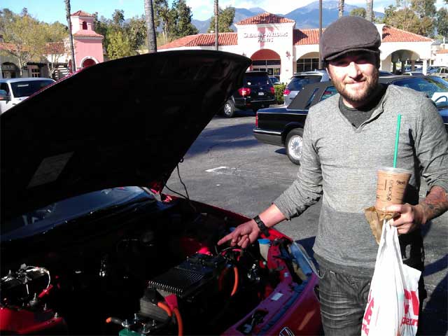
Posted: Thu Mar 7th, 2013 01:26 pm
I drove down and got the plastic today. I quickly put together a grill block-off and will test it out as weather permits.
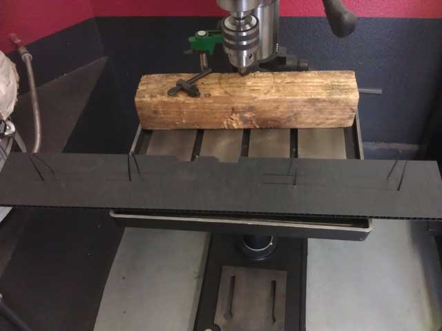
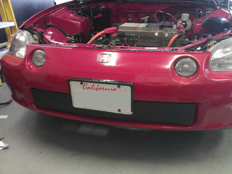
Posted: Sat Mar 9th, 2013 01:44 pm
I
did some informal testing of this new COROPLAST material. The same
sized panel made of this instead of the decking is 7.5lbs lighter. It's
8.5lbs for the porch decking and 1.0lb for the COROPLAST. I will have
to double the thickness on this box due to me already cutting the holes
in the box for the thicker porch decking. But it's still a good 6.5lb
weight savings measure. All while being very strong. I am going to try
and change this material in the interior battery box out tomorrow.
This is also excellent news for the underhood battery box. Even though its already coated with bedliner, if I can shave half an inch off the box height I will be very happy
Posted: Mon Mar 11th, 2013 02:23 pm
I
got the JLD404 meter configured with the normally on connection to the
charger enable circuit. This way I can configure it to open up the
charger enable circuit at a set voltage rather then deal with the 3.5v
adjustment ratio (number of cells) of the charger itself. I still have
the charger configured to charge to a higher (but safe) voltage in case
the meter does not kill the charge enable signal. So as it sits I have
it configured to open the circuit @ 203v and will re-enable the charge
@ 195v. I doubt I willl ever use the lower voltage to re-enable the
charger but you never know.
In the center
console is a plastic filler plug for a OEM switch. I guess it was a
switch for the trans-top option which removed your hard top and stored
it in the trunk electronically. As luck would have it I pushed the
filler plug out and the temp meter for the motor fits perfectly! There
is some minor trimming I need to do but it is going to look great. Then
I will eventually configure that meters relay control to turn on a
motor fan to keep things cool.
I doubt I am
going to replace the decking in the battery box before I go to the DMV
to change the gas code on the registration on Wednesday.
Oh
and the front suspension has settled to 25 1/4 inches to the fender
which is only a 1/4 of an inch more then I had it set before.
And today's energy usage was 2,150 watts over 8.7miles for a rating of 304watts per mile.
Posted: Tue Mar 12th, 2013 04:38 pm
I
could'nt wait any longer. I had the car aligned. Although all 4 wheels
where off it should be no surprise that the right rear tire was off the
most. After all I had to replace that whole knuckle.
After
drawing down 50amps today all the cells measured 3.27v so I guess they
are pretty well balanced after all. I just got worried because at the
top of the charge curve there is such a variance. 3.35-3.50v
Tomorrow is the big DMV day so not sure what to expect. I have heard horror stories all the way to a simple office visit.
Posted: Wed Mar 13th, 2013 08:34 am
Presumed success!
I
arrived at 10:20am for a 10:40 appointment at the DMV. They said no
problem and sent me outside where I brought the car for inspection.
They looked at it, said yup its electric and sent me back inside. The
final person I talked to got up and referred to books and supervisors.
Finally the call was made to convert the gascode to "E" and sent it to
Sacramento for approval. Wow I really hope this works out. Because
after all the horror stories I have read on ther internet I was
expecting the worst.
The DMV says it should
take 3-4weeks to process and I should recieve the updated title in the
mail. I will hold off comments until that is a reality.
Yesterday
I noticed that metal collar I had put in the front spring perch on the
passenger side had fallen out and was loose riding at the bottom of the
strut rod. So yesterday I took the strut off and super glued the metal
collar in place. Luckily that did not affect the alignment.
I also have 25 miles on the car during this recharge and the amps used seems to be lower. I will know exactly how much better after this evenings recharge.
Posted: Thu Mar 14th, 2013 07:59 am
305watts
per mile based yesterdays travel and recharge. I made some controller
setting changes that I think will yield better results, more on that
later. I also drove far outside of my control cycle so its not going to
be the same results as before. I will get to that.
I purchased correct pitch locking lug nuts so the exterior is
starting to look a little more finished off.
I need to trim those plastic panels I had cut for the battery
box because they are a hair to wide.
Beyond that the girlfriend comes into town tonight so I am unaware of how much (if any) progress will be made on the car for about a month!
Posted: Wed Mar 20th, 2013 04:14 pm
Replaced
the copper crush washers on the firewall proportioning valve that had
been questionable with minor seepage for months. The new crush washer
are 3 times as thick and I should have done this a long time ago.
Driving the car everyday. Putting on 30-40miles a day. Still playing it safe with the discharge level until I get more time to monitor per cell.
Posted: Thu Mar 28th, 2013 03:41 pm
I e-mailed EV Netics and asked them if I cut the power cord on the charger and wired it for 220v if the offer was still available to swap it out for the upcoming charger they are going to offer. After not hearing back from them I decided to cut the cord and wire it up for 220v. Then I had some bad info and I got the proximity and pilot wires reversed on the EVC J1772 board. All is great now and I look forward to cleaning up the wires a little bit and increase the depth of discharge level ever so slowly. Doing all this now locks me into 220v charging unless I makes a 110v cable out of a J1772 plug. I have the plugshare app on my phone and a chargepoint card handy if I should ever find the need for public charging stations.
Posted: Mon Apr 22nd, 2013 10:06 am
I
dropped the girlfriend off in TX and now have an open schedule again. I
ordered a new clutch and flywheel friction surface. I will work on
finding the numbers in question on the old clutch regarding a possible
waranty/recall situation after everything is replaced. I dont want the
car sitting apart while I wait on parts.
Tomorrow is another, and hopefully final DMV appointment. They wanted a "statement of facts" on the conversion to electric so they can put it in the system.
Posted: Tue Apr 23rd, 2013 10:55 am
Back from the D.M.V.. I ended up going to another location from the original one and they sent the paperwork to Sacramento (state capital) for further processing. I have more to say on this visit but in order to avoid "shooting myself in the foot" I will hold off posting details until it is processed. I expect a 2-3 week turnaround time to hear any news.
Posted: Tue Apr 30th, 2013 07:34 am
Clutch is due here Friday. Sounds like a weekend project!
Posted: Fri May 3rd, 2013 11:55 am
All
the clutch parts are here. And as a special treat the Powerlab8 came
back from repair so I can once again use it to help bottom balance the
battery's when the time comes. Logic would say wait until tomorrow but
I will probably start tearing the car apart tonight.
After seeing the new clutch, it's fair to say quite a lot of friction material was "gone" from the current clutch. I will have side by side photo's tomorrow.
Posted: Sat May 4th, 2013 08:39 am
Logic never stood a chance, and my memory fails me!
I
removed the motor in record time last night and when 2 flywheel bolts
wouldn't come off, I decided to call it a day. Today I heated up the
Loctite I had used with a torch and then removed the bolts with no
issue. I have NEVER had to heat up a part to remove it after applying
Loctite but due to the fine flywheel bolts threads it was required.
After that was done I replaced the flywheel surface and installed it on
the motor.
Without having the clutch side by
side I was only going off of memory when I said a lot of material was
removed. That is not the case however. It is worn down, but not a lot.
It is however glazed very badly.
I hope to complete this tomorrow.
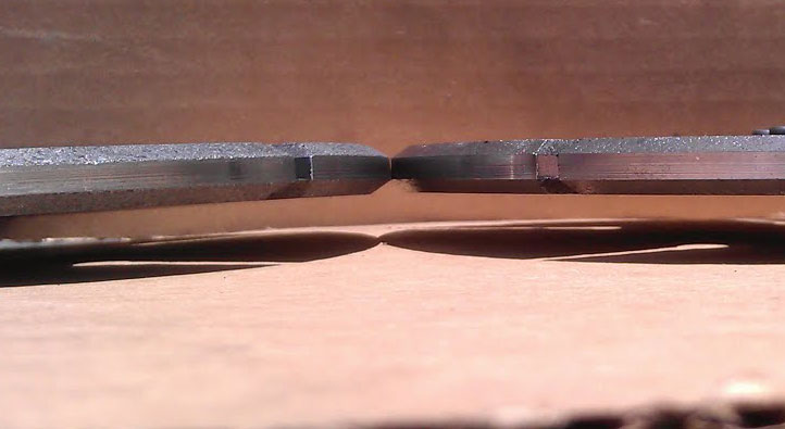
New clutch on left.
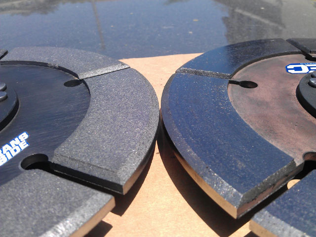
New clutch on left.
Posted: Sun May 5th, 2013 10:16 am
I got most of the work done last night, with only the
connection of a few misc wires which I completed this morning.
Car is great! It's to early to call success but with 60miles on the odometer I can already tell the clutch is holding much better. Per SPEC's instruction I am holding off full application of the throttle until the clutch has 500 break-in miles.
Posted: Mon May 6th, 2013 04:11 pm
Rained all day and tomorrow looks no better!
Posted: Tue May 7th, 2013 11:47 am
I
found sunlight today! 25 more miles where put on the car. It dawned on
me the reason that SPEC advises of a 500 mile break-in is so that it
will wear while going through the gears. I usually just leave the car
in 3rd gear so for the time being I am rowing through the gears from a
stop. This will not be the long term solution but just until everything
is seated.
I noticed today the clutch doesn't fully disengage. If I have the car in 1st gear and the clutch pedal depressed it will move forward with a little throttle. No idea if that's just the master cylinder that heeds bled or not. I don't think that is a concern at this point.
Posted: Fri May 10th, 2013 06:29 pm
With
140miles completed I am going to make it a point to put on as many
miles as I can this weekend. I am set to take an extended vacation next
week and would like to have more miles on the vehicle before then.
With the ability to use more throttle then before I am finally heating up the controller, though never enough to turn the fans on. I can now confirm the temp gauge is not working to display the controllers temperature.
Posted: Sat May 11th, 2013 01:02 pm
Put 45miles on the car today. The clutch is becoming easier to go through the gears. This stands to reason that there shouldn't be any "new" problems as the last clutch was fine with going through the gears. Of course I may have not noticed the smoothness until the clutch started slipping and wore material off the surface. Going to do the same thing tomorrow and also work on fitting a sheet of plastic under the car to streamline things a bit.
Posted: Tue May 14th, 2013 05:49 pm
Haven't
done the plastic yet. I have 320 miles on the clutch and have found the
happy medium to leave it in 3rd gear around down unless starting from a
stop on an incline and then I choose 2nd. @ 65-70MPH I use go to 5th.
I
am starting to slowly allow more throttle application while
accelerating. I can tell this will be a fun car with full throttle 4th
gear roll-ons!
I hope to get a couple hundred more miles on the car in the next couple of days.
Posted: Wed May 15th, 2013 07:46 am
Drove the pack down with 70AH removed. And going by simple math that would be 70% discharged from a 100AH cells @ 188v for the pack. These cells are always higher then the rated capacity however. Every cell measured 3.243-3.248v which according to the charts on the EVTV website puts them about 60% discharged. So its safe to say the pack is balanced. Tomorrow maybe 75AH removed from the pack and measure every cell again.
Posted: Wed May 15th, 2013 01:39 pm
After rest, setting up for the nightly charge the pack recovered to 189v and 3.25* per cell. 75AH is the new cycle target!
Posted: Thu May 16th, 2013 09:58 am
Not enough time in the day, or enough days!
With 370 miles on the new clutch I drained 30AH out of the pack after a recharge I and then broke connection of the pack for safe storage.
Posted: Wed Jun 12th, 2013 04:00 pm
Alas I have returned.
I will post updates as I find time to sleep.
Posted: Thu Jun 13th, 2013 09:18 am
Here is where I am with the car.
I
need to get the front underhood battery box mounts fabricated and
mounted. Then relocate the battery box that is temporarily located in
the trunk to the front. The box is coated and drilled so its ready to
go.
I also have an airbag light illuminated
and horn that do not work. I know the problem, somehow when I replaced
the steering rack the wheel got "off" by one or more rotations. Because
of that it snapped the clock spring/reel spring under the steering
wheel airbag. I found a used one guaranteed to work, due here tomorrow.
The
rear battery box will be the most complicated and also the most costly.
That will be the last of the boxes. No idea on time frame for that.
The
air conditioner pump will be installed when I have a larger front motor
mount plate made. I don't know what else I am going to need to power so
I had a 1/8" steel plate made for the time being.
I
need to mount the Elcon 2500 battery charger on the trunk firewall. I
then also need to buy another identical charger to mount next to it.
That will make a 5KW charging potential which I am satisfied with.
I still need to mount the plastic sheets under the car to
improve aerodynamics.
I
need to figure out a long term 12v power solution. Either a DC/DC
converter to take pack voltage down to 13.5v or run an alternator.
I
need to buy and install a air blower for the motor to come on at a
predefined temperature, to be controlled by a display with a relay
output I bought online from light object that needs to be mounted in
the center console.
I need to mount this new swifttech coolant pump and plumb up a
cooling system for the Soliton1 controller.
I
need to secure the interior battery box with another bolt. I only have
it secured on one side because I couldn't find the other one and I
wanted to drive the car around. I also need to replace the decking
material at the bottom of the box with the lighter weight corrugated
plastic panel.
With 430miles on the new
clutch I am slowly increasing the power to the motor (done by my foot
not the controllers software). Having 3 front wheel drive cars before
by preference to RWD I am all to familiar with "torque steer" under
rapid acceleration. However because this motor spins counter clockwise
its the first time I have it pulling the car to the right.
I am having way to much fun driving the car around in its current condition. The local STARBUCKS and frozen yogurt shop are good locations to go "EV trolling" as I call it.
Posted: Sat Jun 15th, 2013 02:10 pm
Yesterday
I installed a new cable reel/clock spring behind the steering wheel. It
was about an hours work even without instructions. I am happy to have a
working airbag and horn again!
Today I finished 500 break in miles on the new clutch. I am still going to take it easy and slowly increase the power. I should get some video up soon showing antics.
Posted: Tue Jun 18th, 2013 03:30 pm
I
drove the car for 40 miles today and that corresponded with 43AH
removed from the pack. I was not easy on the car a couple times and
that really sucks energy down. I am telling people it is a 75mile range
car (on paper). We will see as the days progress if that is a factional
reality.
I went to a local car show today and was met with receptive
comments about the car. This may become a monthy thing for me.
The next thing I want to get done on the car is plumb up the Soliton1 controllers liquid cooling. I have most everything I need besides some fittings which I can get locally.
Posted: Fri Jun 21st, 2013 06:59 am
I
got around to placing plastic sheets and making a undertray of the car.
However I removed it! I think sealing up the engine compartment is not
a good idea at this time with no forced cooling of the motor. I am also
heavily considering the removal of the front air dam block-off. I think
the aerodynamic drag is a worth while offset of a motor with a
prolonged life!
While under the car I once
again cleaned off more grease/oil from the gas motor. I realize its 20
years worth of build-up but I continue to be amazed at the level of
filth. I am happy this wont be a reoccuring trend, however.
Brief tidbits of info:
The
best possible 0-60 times will be obtained with leaving the car in 3rd
gear off the line. The max speed in 2nd is 40MPH and 3rd is 65MPH. I am
careful to apply a steadily increasing amount of power and then floor
it once the car is going 25-30MPH. With this method and using very
unofficial level of measurement the best I can say is a 8 second 0-60
time. Which I think is pretty good for an electric car. It's no TESLA
but hey!
The car has 700 miles on the new
clutch and it feels like it will hold. There is a urge to increase the
Soliton1 controllers slew rate from 200 to 250. Hmmm
New picture of the swifttech pump that is a plastic version of the Laing D5 pump that has become popular to use for this application.
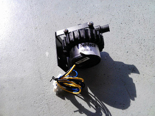
And a picture from the car show
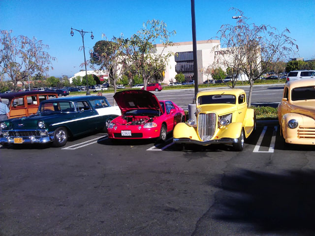
Posted: Sat Jun 22nd, 2013 02:32 pm
Still more picture catch-up.
The Honda Del Sol airbag clock spring:
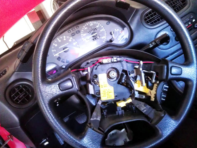
And I was able to get the center console hole filed enough for a perfect fit of the JLD7100 temp guage for the Warp9 motor. I will get that hooked up as time alots.
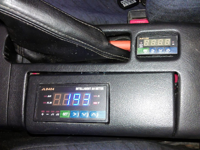
I removed the front air damn block off and am now enjoying a cooler running motor.
Posted: Wed Jun 26th, 2013 01:21 pm
Not to get all political on everyone but I think there is a
cause that deserves your attention!
Please sign the petition to protect Tesla motors from a
distribution ban. The petition is @ https://petitions.whitehouse.gov/petition/allow-tesla-motors-sell-directly-consumers-all-50-states/bFN7NHQR
Please have a voice in this matter! This may seem like a simple fight but "big oil" is backing the OEM's to try and stomp this out. Most recently in NY but many states are to come I am afraid.
Posted: Wed Jun 26th, 2013 04:02 pm
Today
I called the California DMV Special Processing Unit (SPU) to check the
status of the title and registration. I am happy to find out a new
title and registration has been printed and due to be sent out in 3
days! They also mentioned a refund of an unknown dollar amount in
registration fees do to the change to electric mode of power. I can't
imagine it being a noteable amount, in fact I can't believe the state
wants to refund any dollar amount.
The car
has 900 miles on the clutch. And pretty soon here I will turn up the
controllers acceleration slew rate to 250 from 200. I have entered the
derating mode with the Soliton1 controller so I need to move forward
with liquid cooling it.
All this however will have to wait. As other ativities will keep me out of the state.
Posted: Fri Jun 28th, 2013 01:58 pm
OK
one last post. I did turn up the slew rate on the controller to 250.
Everything "seems" to be holding together! Nothing like flooring a car
in 3rd gear going 30MPH and laying a strip of rubber on the ground.
Having Corvette's in the past, I am akin to this much torque. However I
am not used to having peak torque at 0RPM!
The clutch now has 1000 miles on it, I am happy.
Also
guess what came in the mail? The new title from the state of
California! The gas "code" has been changed to "E" and the charge was
$0.00! I am still waiting to see that refund check. I won't hold my
breath.
I have all the remaining parts written down to liquid cool the controller. It just comes down to a few fittings and line, I have everything else.
Posted: Wed Jul 3rd, 2013 03:26 pm
I am back.
Looks
like the TESLA petition got the required 100,000 signatures to warrant
an official White House response, looking forward to that.
I
went ahead and ordered the parts (hoses/fittings/reducers) required to
liquid cool the controller. I figure its coming from JEGS home base in
OH so its due here on the 10th.
Thus years
EVCCON held by EVTV is coming up. I had actually registered to BRING
the car to the show. It's looking more and more like that will not
happen. So tomorrow I will cancel my hotel and registration.
I will not have the car done in what I consider a presentable condition. I am a bit of a perfectionist and I cannot get everything I need done to the car in a month. So rather then rush and half-ass it I will take my time.
Posted: Mon Jul 8th, 2013 12:57 pm
I
waxed the car for the first time today. It what I consider a half
hearted effort by NOT claying the paint I still spent 5 hours making it
look good with Zaino polish.
I also ordered new tires for the car. This was a long time coming. The OEM Del Sol size is 185/60/14 and I currently have 185/65/14 on it now. These where the tires I got with the Civic HX wheels and I wanted to run those down before replacing them. The new right sized tires have a sidewall height of 4.4" VS the current 4.7". So other then changing the gear ratio and ride height ever so slightly, everything should be the same. Maybe it will be "enough" to start the vehicle in 4th gear every time.
Posted: Wed Jul 10th, 2013 03:18 pm
Everything came in as scheduled.
So tomorrow the car gets new booties (tires) put on. I will
just bring the loose rims and tires to the tire shop.
And
if I find the time I will try and mock up the cooling hose path. I put
the fittings with Teflon tape on the Soliton1 controller, but that it.
On
the two pipes coming from the radiator I am going to have to work with
some angles. The 1 1/4 adapter has a -8 AN fitting, this was the
smallest I could get. From there I have to reduce it to a -6 AN and
then to a straight connector. This proved to be to long and to close to
the shunt next to the controller. So to avoid this I am going to do a
90degree angle fitting coming of the radiator pointing downwards. It's
not the way I intended to do this but it works. The flow restriction
from the angle it not a problem either. Its going to 1/2" line anyhow
from 1 1/4" hose.
The webhost is down for a moment so no pictures! I will update
it when they come up.
I also noticed the "SRS" airbag light briefly illuminating. I will have to watch that! Not great news.
Posted: Thu Jul 11th, 2013 11:12 am
I
have the new tires installed, love it. The ride is much better a lot
more quiet. I also noticed its not as hard to turn the wheel on
pavement. So there might be a contact patch reduction.
I bought some schedule 40 standard PVC 3/4 90degree elbows to help mount up the radiator connections. However it was to late in the day to get a 9inch piece of 1 1/4" radiator hose so that will have to wait until tomorrow.
Posted: Fri Jul 12th, 2013 02:24 pm
The
straight hose I was waiting for came in. Sadly this hose was not flat
all the way through. It has corrugation and a inner metal spring to
prevent it from collapsing under heat. This won't work for me. So the
only other choice was a 3 foot section of hose due to arrive tomorrow.
I contacted the seller on ebay about the "clock spring" failing. He is honest enough to send me another one out at no charge. I will get that installed this coming week.
Posted: Sun Jul 14th, 2013 11:07 am
After
a couple screw ups from the parts place, I got the right hose. However
with 1 1/4 fittings everywhere else I had planned idea of "building up"
the 1 1/8 outlets on the radiator to make up the space, instead I went
ahead and ordered another radiator with 1 1/4 fittings already in
place. Of course this radiator has a larger core and make out of
aluminum. Probably overkill for the situation but at least it will look
pretty.
For the time being I am not going to
hook up the heater core. I do not want to run coolant lines until the
battery box is installed underhood.
So back to waiting for parts. Until then I am still driving the car daily.
Posted: Tue Jul 16th, 2013 12:53 pm
The radiator came today and I put it in. Now I am running hoses and fittings. Still haven't found a place I like to mount the pump. The radiator is twice as thick as the OEM one. Not wanting to trust the radiator cap they included with the radiator, I used the original Honda one.
Posted: Thu Jul 18th, 2013 01:53 pm
Liquid
cooled delight! I was able to get the pump and hoses finally squared
away. The big radiator is cooling the controller by itself. And from
driving it around today, its not even heating the coolant up that much.
I am glad I didn't route it to the heater core in the car, it would
have been pointless. This makes installing the underhood battery box
that much easier. I bought 6 feet of 1/8" 6061 aluminum angle stock to
play with and make a temporary water pump mount. I feel fairly certain
this metal is strong enough to hold the battery box so I think I may
pursue building a battery box shelf out of the aluminum and not steel.
The
controller is now cool to the touch and never goes into thermal
de-rating. The coolant in the radiator itself stays not even luke warm.
Maybe an extended run will yield different results.
Now I am tempted to turn up the slew rate another 50amps a second to 300
Posted: Fri Jul 19th, 2013 07:48 am
I went and took 30AH out of the pack in 20 minutes of spirited driving, all trying to prove a point. First thing in the morning before driving I took an infrared thermometer reading of the side of the radiator. The measurement read 78F. After the driving with the controller still cool to the touch I measured 79.5F from the same point on the radiator. That settles that. The controllers heat cannot be used as a source of heat for the cabin.
Posted: Fri Jul 19th, 2013 06:50 pm
I
went to change the slew rate to 300 and to my surprise it already was.
I guess you cannot set the menu for odd digits. I set it for 250 again
and when I saved it had jumped to 300. I think I will leave it at that
for now.
I changed the second output on the Soliton1 to "water pump" from "controller temp". I never got the controller temp to display on the factory gauge anyhow. I will run a wire from the relay still mounted on the firewall I was going to use for the brake pump to the water pump tomorrow.
Posted: Sat Jul 20th, 2013 03:42 pm
Got
the coolant pump hooked up to a relay controlled by the Soliton1
controller. Very happy with the car, given how incomplete it is.
I
am really hoping I find room to install 2 more battery's. You can tell
the difference (albeit slight) between a fresh charge and 20-30AH
removed from the pack. A couple more battery's would bring the voltage
up during those times. This would, of course, mean re-bottom balancing
the entire pack. I am OK with that as there is still the matter of
replacing the material in the bottom of the inside battery box with
lighter weight corrugated plastic.
There is an open source EVSE project that I have interest in @
http://www.kickstarter.com/projects/emw/emw-juicebox-an-open-source-level-2-ev-charging-st
Basically for $600.00 it comes preassembled with a 70A J1772 cable (bought separately) you get a 60A charger! About a third of the going price for a similar unit from Clippercreek! This is TWICE the power of the GE Wattstation. Of course your car has to require that much power for it to be any benefit. I don't see the Del Sol ever requiring more then 28A (2x Elcon 2500 chargers @ 14A). But just thinking for the future.
Posted: Sun Jul 21st, 2013 12:19 pm
I
was feeling generally good about the car today. Being that the
controller is now liquid cooled, its a load off my mind. So much in
fact, I decided to take the car on the mean EV streets of Southern
California (aka the freeway). I went down a couple of exits on the
freeway and the car felt great. I do think the front end sits up to
high and cannot wait for that to be revised with the battery's
underhood and/or suspension modification.
To
avoid creating havoc by setting the cruise control at 63MPH I put a
sign in the back window that read "Testing Electric Car". Everyone got
out of the way and not to many haters who dove back into your last one
they pass you. This run ended up covering 33 miles total.
Oh
yeah. In others I got word from Sebastian from EVNETICs that the
charger/DC converter I was waiting for is still a LONG way off. This is
a bummer as I bought the Elcon PFC2500 charger to "get by" until his
was complete. I will still continue with the plan of configuring an
identical PFC2500 charger and run it in parallel with the existing one.
The one thing that does leave up in the air is what to do for 12v power. Right now I am independently charging the 12v battery every time I recharge the high voltage pack.
Posted: Tue Jul 23rd, 2013 06:22 pm
With
33AH removed from the pack today I disconnected it and removed the box
that was in the trunk to put underhood. I found a fabricator for the
mounting rack that is local. I am going to take the box to him and ask
that he make it as wide as the box, but 31.5" long which looks to be
the width of the strut towers, while leaving room for attachment points
with 1" wide bar stock.
I am going to try
using 1/8" aluminum angle stock to hold the 130lbs of batterys and box.
Unless I hear differently tomorrow. I am also going to try and mount
the box as is as low as I can above the transmission. But I do have the
option of removing about an inch of material from the top of the box by
using thinner corrugated plastic for the box bottom.
Once I know the mounting rack and battery box fit I plan on coating the rack in bedliner. Now that I think about it the added weight of the bedliner may negate some of the weight reduction of going with 6061 aluminum. Hmmm
Posted: Wed Jul 24th, 2013 10:42 am
The
rack is being made. I heard 1/8" aluminum would not suffice over such a
long 31.5" span. So instead I opted for 1/4" 6061 aluminum. The shop
then stated that 1/8" steel angle iron would not work. Don't know if I
believe that but I will take their word on it.
It's supposed to be completed in a week. All that's left is to
get 1" wide bare stock to make some hangers.
While the car is lifeless it gives me time to "catch up" on the net solar energy, and to ride the electric bike.
Posted: Thu Jul 25th, 2013 08:54 am
I
mounted the charger to the old bottom to the underhood battery box (I
am replaced it with thinner/lighter corrugated plastic). Then I affixed
it to the wall of the trunk. Then of course I had to extended the
factory wiring for the charger enable circuit to the JLD404 display.
Now I am trying to reconfigure the battery's around in the wood box in the trunk so that the cables reach. I could easily get a longer cable but figure its better not to waste the money on more cables until all the battery's are were they belong and in proper boxes
Posted: Thu Jul 25th, 2013 01:38 pm
The battery's are reconfigured in the box. Since the pack battery string will now start from the front of the car and not behind the seats, I will need to redo the positive charger lead. The negative is OK as the pack will still "end" in the trunk. It's really just an excuse to drive down and buy more goodies from EVWest!
Posted: Thu Jul 25th, 2013 04:19 pm
OK I am just going to embed images from my blog until I get this ftp host situation handled!
The aluminum Del Sol radiator: 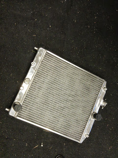
My wacky PVC connection for the radiator to AN fittings: 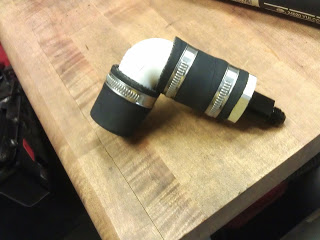
Radiator mounted with factory Honda overfill bottle: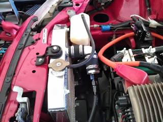
Another view 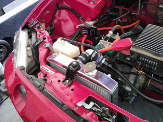
Elcon PFC2500 charger mounted on the trunk wall: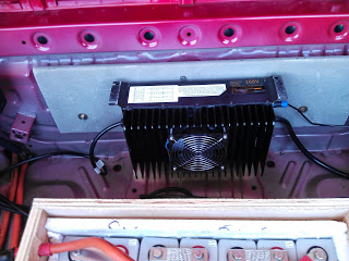
Posted: Fri Jul 26th, 2013 06:25 pm
Don't
know why I didn't think of this earlier but I am going to hook up the
charger connection from the cables coming from the controller. This way
its on the other side of the shunt and will "count down" the amp hours
until fully charged. It's my understanding that it is not as accurate
going into the battery as it is coming out. Either way I kind of have a
feeling for what level the pack is at based on voltage. The pack sits
at 196 forever then jumps to 197 for 10 minutes and then rapidly jumps
from 198, 199 and finally cuts when it hit 200 volts all in a span of
about a minute. I am seriously considering just killing the charge at
198 volts.
Either way this will require a
new 13ft charge cable to be made. Along with that I am thinking about a
2ft Y cable for when I get the other Elcon PFC 2500 charger
ordered/installed.
Maybe Monday the front battery rack will be done.
Posted: Mon Jul 29th, 2013 04:20 pm
I
happened to be somewhat near EVWest today so I dropped in there. I
think they got the gist of what I want to do. So the parts where
ordered to make me 13ft charger leads and a "Y" cable for the future
addition of another charger.
I will call about the battery rack tomorrow.
Posted: Fri Aug 2nd, 2013 12:03 pm
The rack is complete. I picked it up today and it came out better then expected. If I had done is, I would have simply overlapped angle stock over the corners. This was a professional job that cut the stock at an angle and then welded through both side for strength. On the way home I stopped by Fastenal to get a 6' section of 1/4"x1" steel bar stock to make hangers for the box. Oddly enough they showed inventory in stock but could not be located. So it was then ordered for Monday delivery.
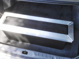
Bottom of rack mounted on box.
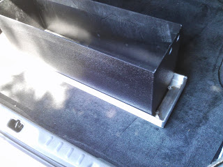
Top of rack with box installed. Even amount of room on both sides of box for bolt placement for steel hangers. Rather then bend the steel I am going to see if I can space out any tolerance differences with washers or metal collars.
Posted: Mon Aug 5th, 2013 10:22 am
The flatstock material was backordered so its now expected on
Wednesday.
That same day I am meeting with the Mayor of the city of Mission Viejo to discuss EV vehicle charging infrastructure options to residents. I am in no way qualified to be an expert on the matter but the Mayor said that's kind of the angle she is looking for.
Posted: Thu Aug 8th, 2013 01:06 pm
I guess my post yesterday didn't save.
I got the flat stock and immediately began work of tray placement and measuring to ensure fitment. Man this is going to be tight! I now wonder if I shouldn't have just done a single row of battery's in the box. Well what's done is done. Now to work with what I have. I had to remove the A/C hard lines AND the 12v battery tray (which thankfully came out with 3 bolts). This was not planned. Now I may be forced to reduce the box height 1 1/2" which I am OK with. I could actually go more if I had to my removing the false bottom in the box altogether and resorting to securing the battery box from the side into the aluminum angle of the battery box tray.
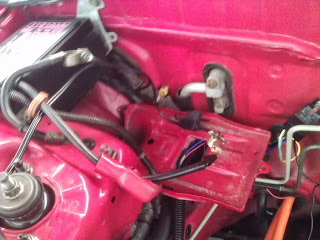
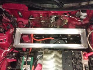
This was all after I had an hour long meet and greet with Rhonda Reardon the mayor of Mission Viejo, Ca to discuss electric vehicle charging. She was insightful in the thoughts her committee had on EV's. Even a couple I hadn't heard before. After all was said and done I think the subject may be revisited in the future, especially after I X'd out 16 of the 23 charging stations located within a 13 mile radius of the city. Those units where either not public, not working, high usage rate or removed altogether!
Posted: Fri Aug 9th, 2013 03:18 pm
I
think I can mount the battery box in the rack without cutting it down.
I was able to gain the necessary couple inches of clearance by routing
a wire harness UNDER the front right brake line on the strut tower,
rather then over the top. This protects the wires also. It took
removing the harness from the sheet metal attachments end electrical
connections all the way up to the front of the car and then routing it
back. I was able to set the tray and battery box in place temporarily
and close the hood with an inch or more to spare!
So
I need to cut the flat stock, drill it, drill the battery tray, mount
everything and check fitment, make the final holes to mount the battery
box to tray, check fitment, tear it all apart and coat it in bed liner,
clean up the holes where bed liner coated, reinstall it, get the long
run cable from EVWEST so I can charge the pack, then this phase may be
complete. There is a lingering airbag clock spring that I have been
avoiding for some unknown reason.
The wire harness I re-routed under the brake line for extra space
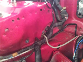
Box fitment looks good:
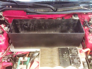
Looks can be deceiving, the hood does close:
![]()
Posted: Mon Aug 12th, 2013 04:20 pm
Life outside the Del Sol has kept me occupied big time! So things are progressing slowly. Until then..
Posted: Thu Aug 15th, 2013 02:35 pm
I have some bolts to start the fabrication.
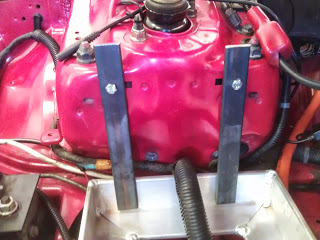
On the left side (facing car) the 2 hangers are going to go on the inside of the rack.
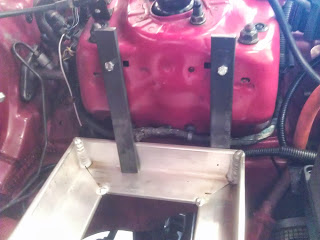
But on the right side because of the angle it fits better on the outside of the rack. This is why I had the rack built with an inch on either side to spare. Once I get everything mounted up I will trim off excess metal on top and make it look cleaner.
Posted: Sun Aug 18th, 2013 03:04 pm
Happy Days! The battery box is mounted!
My
concern for creating those side support bars for the hangers where
unwarranted. This thing is rock solid. Until everything is tested I am
not going to coat the parts yet, and even then I am going to opt for
black paint rather then bedliner.
Now all I
need is a charging cable which EVWEST has created, I just need to go
pick it up. Oh yeah and I guess put the interior back together.
Posted: Tue Aug 20th, 2013 12:06 pm
I have a picture of the box:
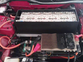
I had to file down the bedliner on the edge's where the welds beaded up on the box. Other then that it fit great. I secured the box to the rack with low profile 8mm bolts I had from installing the new SPEC clutch surface. The ride height looks perfect! I can't wait to see if this helps the car "hook". There is still a lot of cleanup to do but I want to make sure this works first.
Posted: Thu Aug 22nd, 2013 12:28 pm
OK
not to leave everyone hanging, but..... I have had a bad cold the past
week and I am still trying to "kick it". Add to that another vehicle
purchase I just made and trying to ready for use.
I have to mount the 12v battery and run the charger cables that are already made. It's not a lot of work normally but is like climbing a mountain right now!
Posted: Sun Sep 1st, 2013 09:23 pm
I
finally got the car back together. It rides much better having all that
weight over the front wheels. I didn't get a lot of time on the car yet
as I had to track down why the car wasn't charging (enable signal
wasn't hooked up) and I didn't get that addressed until just now.
If everything is ok after a couple of weeks I will tear down the battery rack and paint it black.
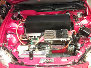
Then its 1 more battery box to go!
Posted: Mon Sep 2nd, 2013 11:27 am
After
a complete day of driving I am happy with this installation. The car
drives and rides like a heavier vehicle and no longer "bump steers"
when hitting uneven objects in the road with the front wheels. It also
rides quieter due to the chassis squeaking less. Before you could hit a
offset speed bump or enter a driveway at an angle and exhibit chassis
flex noise.
I am already convinced this setup will provide good results. But I am still going to put some more miles on it before calling it a total success.
Posted: Tue Sep 3rd, 2013 08:34 am
I had heard that the JLD404 meter was less accurate in the reverse direction (applying power rather then removing). Now that I have the charger configured to charge the pack from behind the shunt I had a chance to test this out. Its really only useful to see how much power has been added pack into the back and reverses the AH countdown that I use to gauge the packs capacity. With 50AH removed from the pack yesterday I charged the pack fully and only ending the charge with -1.16AH remaining. This will certainly add up over time if left uncleared. However it does give me a chance to do a partial recharge of the pack while having a very close approximation of the remaining capacity.
Posted: Mon Sep 9th, 2013 07:26 pm
Car
is great! I am confident in removing rack parts for final paint an
fitment when I find the time. I am still putting 40+ miles a day on the
car. And more in succession as I feel brave.
I am also thinking about making a emergency 110v recharge cable out of a new 50ft 12guage extension cord that is terminated with an Anderson 50 connector that can be plugged into the car charger in a bind.
Posted: Tue Sep 17th, 2013 11:56 am
After
a more detailed measurement, gone is the notion of perhaps using the
OEM fuel tank to house the remaining battery's. Instead I will have
another aluminum box made with the battery configuration as follows.
From the front of the car towards the back. 9 batterys stacked sideways, 6 batterys stacked sideways, 2 batterys stacked longways, and 1 battery longways followed by another 1 battery longways. I will now attempt to depict this in ASCII.

Imagination is a requirement but try and keep your mind out of
the gutter!
And this is so great, I typed this in NOTEPAD, upped the zoom in the browser, took a digital photo with my phone, edited it to auto balance the colors, then uploaded from my phone to my blog, and finally hyperlinked it from there. Where there is a will....
Posted: Tue Sep 24th, 2013 04:24 pm
Interesting
note: I got the Del Sol with 72k on the odometer. And I didn't run more
then 1 tank full of gas before tearing it apart. So lets just be safe
and say 72,500 miles is where I started. ( All this will be checked
later with photos I have on record) I say this because today the car
turned over 75,500 miles. That's 3,000 miles under electric power. Of
course a lot was testing at various voltages but they are electric
miles none-the-less.
I obtained 2 large sheets of cardboard from a neighbor who was doing a home remodel. These will serve as material to make a mockup of the final battery box in the upcoming weeks. I still have a house guest who is taking up any free time.
Posted: Wed Oct 9th, 2013 03:43 pm
OK I am back. I am growing increasingly comfortable with the charge termination point set to 200v with the JLD404 meter killing the enable signal to the charger. If I forgot to hook up the meter the charge curve is still set to terminate @ 201.5v in the charger itself. Still less then the 203v safe charge point. I figure with napkin math I am losing 2.5mi of range by not charging to 3.65v per cell @ 211.7v but I am gaining a lot of cycle life for the batteries to last longer. I am even undercharging them to 3.44v per cell.
I still have the final battery box to fabricate up, have EVWest make me a shorter cable from the underhood battery box to the shunt, lower the underhood battery box mounts to give me more hood clearance, paint battery box mounts, figure out the DC/DC converter situation, figure out long term charger solution, etc. I get asked when will it be done and I honestly tell them never. As there is always SOMETHING that can be improved upon.
I returned from LAX airport yesterday and was surprised by my count of 18 TESLA Model S electric cars on the 80 mile trip home!
Posted: Sat Oct 19th, 2013 11:30 am
I ended up going with a former employee I worked with to check out the TESLA store in trendy Fashion Island in Newport Beach, Ca a few days ago. We walked in to find 2 eye candy women who looked to be a just pretty faces. They knew basic knowledge but sounded like info I could just find in the website. However close to leaving I bumped into a TESLA man who I could totally talk geek to. I developed an immediate bro crush on this guy because he was talking details about things that I wanted to hear. We ended up leaving very informed and it was a great visit! A total change from car dealerships of yesteryear with no pressure, but isn't that kind of the point? Radical new car, and radical new way of marketing and selling them.
OK now back to the Del Sol. With my girlfriend back in TX I have more time to complete this.
I removed a couple more fuses I found and also replaced a couple with lower amperage ones to extend my 12v battery life between recharges.
I
am also pursuing an idea about mounting a flexible 60w solar panel
under an acrylic top on the car to keep the 12v accessory battery
charged. A lot of variables there, I tried to convince the maker to
make one in clear but it lacks the UV protection that the tinted
material has. Also is the loss of it being tinted still enough to make
serious power? I am looking for about 2amps of power. However that
comes about.
I also loosened the underhood
battery rack and pushed it towards to firewall ever so slightly. I then
tightened everything back up. This minor correction prevents the
battery box from rubbing on the hood and thus saves me some labor
redoing the mounting straps.
I am putting about 40-50 miles a day on the car. Not because
that is the battery range but rather that is all I ever do.
In the meantime I am just enjoying the car!
Posted: Wed Oct 30th, 2013 04:29 pm
Let us revisit the charging scenario once more. Right now my electric company (SCE) this time of year specifies peak use from the hours of 11am-6pm. With the current car charger being an Elcon PFC2500 that equates to 2.5KWH during recharge. I am fortunate enough to only incur the peak electricity rates during 4-6pm. These are the hours the solar on my house falls off from generating at least 2500w to offset the charger. Now says I double up on the charger and add another PFC2500. That will be 5.0KWH of use during a recharge, falling short of what my 4.0KWH solar is capable of offsetting. So is it that important to charge twice as quick if I have to push ALL CHARGING to when the rates are off peak. I struggle with this. A solution I guess is to have the ability to disconnect one charger but that adds a level of complexity I had not foreseen or am fond of.
I started to put some more
original carpet pieces back in the trunk. The has suppressed a lot of
road noise in the interior cabin. So much so in fact, I have found a
weird clicking sound under the dash that is induced under hard
acceleration. It clicks on when I accelerate and then clicks off when I
remove application of the throttle. It sounds like a relay. There is no
connection from the throttle cable to anything under the dash. Nor is
there anything in the engine compartment besides the cruise control
(which I doubt sends any signals) and the throttle wires going to the
Soliton1 controller. The only thing I can think or is perhaps this is
based off a speedo signal from the dash. I found more things to
disconnect today under the dash. The fuel pump relay and 2 other
unknown relays but it did not affect the power windows, signals,
hazards, HVAC blower, so I figure it was unneeded. I looked online for
a schematic and although I found many, I did not find the one specific
to the area under the driver kickpanel.
I still have many little things to do on the car when I find the time. In the meantime the website ftp situation has been fixed and I am prepared to offer an onslaught of pictures for your viewing pleasure. There are so many I doubt I will have the patience to tag them with notes. I will post a link when I get the gallery built.
Posted: Sun Nov 3rd, 2013 04:33 pm
80
miles put on the car today. That was with a mix of 2 charges. I also
took the time to blow the motor brush ports with compressed air from a
compressor. A fair amount of carbon dust blew out and until I devise a
cooling fan solution blowing into the motor this will become a monthly
occurrence, which I am OK with.
I am rethinking the solar panel roof idea. I just don't think
there will be enough power to justify the expense.
For fun I hooked up a multimeter and checked for a frame leak from the battery pack. I noticed a 113mv leak. Over time this is not good. So I routed my cable that I had from the underhood battery box to the shunt differently. I had it looped around a couple times because the cable is to long and had the excess laying on the transmission case. It has now dropped to 11mv which is more livable for the time being.
Posted: Mon Nov 4th, 2013 05:09 pm
As promised, the web gallery. http://www.techvelocity.com/delsolgrouped/
Posted: Wed Nov 6th, 2013 01:03 pm
I turned up the slew rate in the controller from 300 to 400amps per second. Its funny how these little setting changes the car SO much. Anyhow I think 400 will be the setting I keep for a while. Anything higher and I think I will start breaking hard parts. I am imagining axles and differential gears finding there way through the hood. Not really, but it paints a funny picture.
Posted: Fri Nov 8th, 2013 04:04 pm
Seems
like that little slew rate change has now changed the preferred gear I
start from a stop in city driving. I had preferred starting the car in
third gear. Now starting the car in 4th gear is not only possible but
doesn't feel like its stressing the car to much.
The 93-95 Del Sol OEM P20/B000 Honda 5 speed transmission comes with the following specs:
1ST GEAR
3.250
2ND GEAR
1.900
3RD GEAR
1.250
4TH GEAR
0.909
5TH GEAR
0.750
FINAL RATIO
4.250
So 4th gear is the closest to a 1:1 ratio.
Posted: Mon Nov 11th, 2013 02:55 pm
I
opted to get things rolling on the battery box today. A change of plans
however. Rather then devise an oblong box that has turned into an
exercise in futility, I decided on 2 square box to house the remaining
battery's. Why 2? Well I wasn't keen on putting them all in one box
behind the rear wheel. This way I can put a span of 10 battery's in
front of the rear axle on the largest stretch of space I have between
the frame rails. The other reason is by doing this I found space for 3
more battery's in the box that goes in the spare tire well.
So
the long box in front of the rear axle where the OEM fuel tank was will
be 26.75x5.5" and the rear box will be 16x11.25". At the same time I
coat these boxes after having them made I am going to bed liner around
the rear of the car to cut down on road noise. My only concern is the
7.5" of ground clearance on the long slender box that goes in front of
the rear axle. My only reassurance is the 7" of ground clearance the
car has with the factory rear suspension arms. The rear box isn't an
issue as once I have the hole cut in the sheet metal from the bottom I
can slide the box up and down and weld it into place. Now that I think
about it, maybe that rear box that will be welded should be made out of
steel. Not to mention perhaps it will be a stressed member of the
frame. Even though this is replacing thin sheet metal BETWEEN the frame
rails.
So the car is apart until I get (now 2) final battery boxes made. I might take the time to order that other battery charger and get it mounted along with 3 more battery's, and this means having to re-bottom balance the entire pack.
Posted: Mon Nov 11th, 2013 05:15 pm
HAHAHA
flippity flip! Remember what I just said 2 hours ago? Lets rethink
this. I am growing unhappy with the aerodynamics that are going to come
into play with that box in front of the rear axle. It's going to be
like hitting a brick wall to the air under the car. The car is never
going to be an autocross star so I shouldn't be worried about all out
handling. Even then I have those rear coilovers I have yet to install.
So I am NOW thinking about a single 29.5x11.25" box mounted as far
forward as I can in the trunk of the car. Then I will relocate the
charger to the spare wire well. This is also less invasive on the sheet
metal of the car since I wont be cutting a large opening for a box.
Likely just a few holes to secure the battery box.
I suppose if I sleep on it I may come up with a new idea in the morning!
Posted: Tue Nov 12th, 2013 11:11 am
OK
I am good to go, with 1 minor revision. I am going to have the box made
.25" wider to allow for a false back (corrugated plastic) to be used
against the battery's. I am allowing this space to possibly bolt it to
the wall of the trunk. I think I can use the 2 lower bolt holes for
that. And I also think I can make a hanger of sorts for the top center
hole to provide support for the box.
With
everything double checked I ordered 3 more 100AHA battery's from
EVWEST. As luck would have it they had a pending order to submit with
CALB so it works out great.
I will source out the box in the coming days. Until then I think I will put the battery's back in the trunk and drive the car around. It has only 22AH removed from the battery pack according to the JLD404 meter. I will drain that down to 80AH and they manually drain with the Powerlab8 from there to bottom balance the pack again.
Posted: Thu Nov 14th, 2013 11:52 am
The battery box is ordered, the remaining battery straps are ordered, I ordered a couple #1156 LED bulbs to play with. I will put the battery's back in the trunk of the car tomorrow and drain them down in preparation to bottom balance.
Posted: Fri Nov 15th, 2013 10:35 am
I knew the rapid rate of succession could not be maintained! I just got a e-mail from EVWEST saying they are not doing the battery order for at least 2 weeks. What to do..
Posted: Fri Nov 15th, 2013 05:11 pm
Looking
at the charge profiles loaded into the PFC2500 charger I have a couple
of choices that falls into the 213.5v charge voltage range for 61cells
@3.5v each. 212.4v and the next step is 216v.
So
I can either charge them to 3.48v or 3.54v. I think I will do what I
did before and set the JLD404 meter to open the charge enable circuit
on the charger and terminate the charging @ 214v which would be 3.50v
per cell. If I somehow forget to turn the JLD404 meter on, the charger
will still terminate charging @ 3.54v.
I am in contact with a couple of people who have stock of the CALB battery's I need. I will see what develops next week.
Posted: Wed Nov 20th, 2013 12:30 pm
The
battery straps and LED lights came in. The LED light will work perfect
for a backup light but will take a little work on the turn signals.
The white is pure white so the backup lamp is bright.
The
same bulb in the turn signal with a plastic orange lens is another
story. It takes the orange and makes it more of a yellow. This is
reminiscent of the last generation BMW M3. Its livable and I like how
it come instantly on and off. The one thing I am question however is
the rate of succession. The signal blinks about twice as fast as the
factory bulb. Any voltage amps saved with the LED bulb will be surely
negated by this. So I am off to look for a replacement flasher module.
Careful to avoid the "load resistor" type which would defeat the whole
purpose. It blinks normally with the hazards on because there is enough
load to maintain the stock signal speed.
The battery box should be done tomorrow and then I will try
fitment.
All pictures are taken with no flash.
LED rear signal: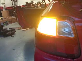
LED reverse light: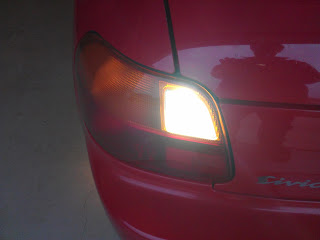
Original Halogen reverse light: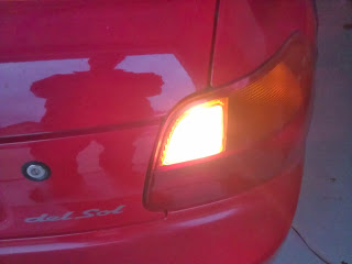
Posted: Wed Nov 20th, 2013 06:07 pm
I have some other shots taken @ night.
LED reverse light on left:
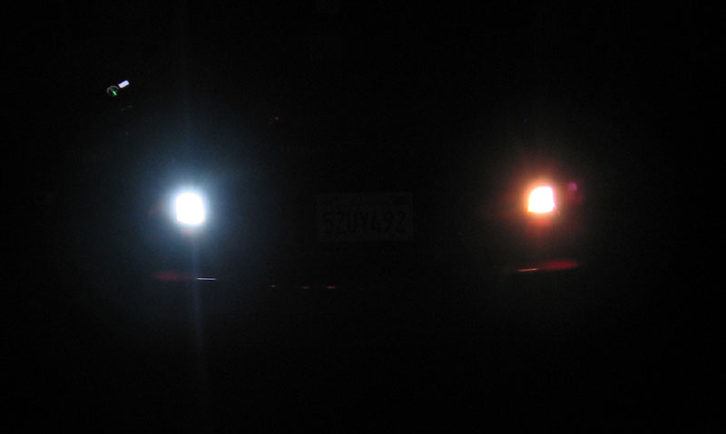
LED turn signal on left:
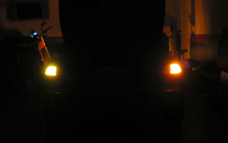
I also ordered a few more LED lights from EVTV to try for the brake lights
Posted: Thu Nov 21st, 2013 12:47 pm
I
really make things harder then they should, but that's kinda my thing.
I located the FR-3501 Del Sol turn flasher / relay in the drivers foot
well against the fender. I removed it and began taking it apart to see
what could be done to modify it. I looked online to no avail for a
aftermarket flasher unit and found none. I was surprised to find this
was a $75.00 unit even on the aftermarket. Why they couldn't have used
a cheap $5.00 3 prong flasher I don't know. So after taking it apart I
noticed each side has its own flasher relay, which is nice. Then I
noticed 2 metal "loops" coming from the PCB. After a little research
online I found out this is the OEM way of adding resistance to the
circuit to control the speed of the signal. Less resistance the faster
and the more the slower. So I ordered resistors from Digi-Key for $2.00
and figure its worth a try. Its time for me to brush up on my soldering
skills!
Up close view with MITSUBA flasher FR-3501 part number and
specs:
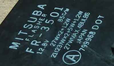
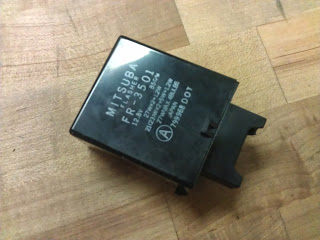
Work a small flathead screwdriver into the seam and work it around the plastic nipples:
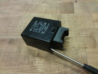
The end piece will come off:
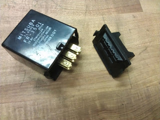
With the end piece off squeeze the plastic from a diagonal angle to work the board loose from the plastic. It is not glued in, but over time its harder to come out. If it does not easily come out you fan use a pair the pliers and pull it out from the board. A work of caution here, you need to insulate the metal pliers from the PCB with a piece if plastic or rubber. If you pull the board out with bare metal piers and it slips off you risk damaging the PCB and the trace connections on the board. Also do not pull the board out from the 6 metal pins on the board. They bend easily and prone to breaking off:
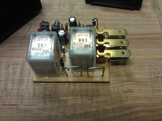
With the board out you can see the two metal loops I will be replacing with a resistor in the lower right.
Posted: Sat Nov 23rd, 2013 11:01 am
The
resistors came today for the relay. I quickly DE-soldered one of the
metal "loops" in the flasher/relay and replaced it with a resistor. I
then tried the left signal with 1 LED bulb and 1 incandescent and they
work perfectly! No more hyper-flash. Then just to be curious I put the
LED bulb in the right signal and tried it. Regular flash in that one
to! GREAT. I looked at the PCB more closely and saw the metal "loops"
share the same common wire. So its the combination of the 2 "loops"
that add resistance to the circuit. Glad I checked before DE-soldering
that other one!
So in the end only 1 of
those metal "loops" need to be replaced. And the easiest one to get to
is the one on the corner of the circuit board. I am going to try 2 LED
bulbs front and rear next week to see if that changes things. And if it
does all I would have to do is replace the other "loop" with a resistor.
I angled the resistor to take up the same space as the stock
"loop".
The part # is KNP100JR-52-0R12
RES 0.12 OHM 1W 5% AXIAL
$0.33 each from DIGI-KEY
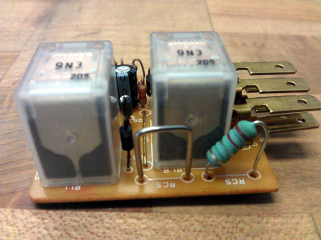
Posted: Wed Nov 27th, 2013 11:13 am
The
battery box didn't happen yet. Its done but I have to arrange a time to
pick it up. The fabricator also does Aerospace contracts that take
priority over this. I am hoping for Friday.
I
received my latest package of goodies from EVTV in the mail today. A
pair of 10W LED bulbs that use 2 CREE SMD LED modules. They have a 3x
refracting lens. I had bought these because I figured if they where to
directional I could always use them for backup lights. It turns out
they are perfect for the rear turn signals. The front turn signals are
another story as they are orange colored bulbs. I will source that in
the coming days. So I now have LED backup and rear turn signal lights.
I will add pictures as I find time.
:EDIT:
The light isn't as spread out as the previous 20W ones I tried. The
payout is these LED lights use 1/2 of the power. I am on the fence
about this one. The pictures will explain.
The 20W LED is on the right. The 10W LED is on the left.
This picture was taken as the light begins to go off, to help
illustrate the difference in beam pattern.
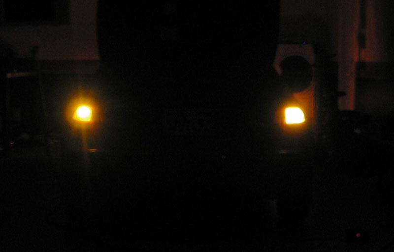
In this photo the lights are almost at full brightness.

Posted: Fri Nov 29th, 2013 03:02 pm
Yeah, nothing yet. Hopefully everyone will be back at work on
Monday to arrange for pickup of the box.
I
have 4 more bulbs to get to complete the changeover to LED's. They are
the dual filament #1157 bulbs which will be used for the brake light
and the front turn signals. One concern however is how "pale" it might
make the light appear. The Kelvin temperature of these bulbs are around
5,000K. The front bulbs have a plastic orange shield that gives the
bulb the amber color. And the rear has the red lens on the light
itself. I guess I will give it a shot and order them. I am thinking
that worse case scenario I can "tint" the glass lens on the lights with
either amber or red to help the look.
From Honda the turn signal circuits are 62W consisting of:
27W+27W+7W+1W 5.16amps @ 12v
That's 2x 27W signal lights front/rear,1x 7W turn indicator
light on dashboard, 1x 1W resistor in the relay
With LED lights the turn signal circuits will be 19.5W:
10W+7W+1.5W+1W 1.62amps @ 12v
That's 1x 10W rear light, 1x 7W front light,1x 1.5W indicator
light on dashboard, 1W resistor
And brake lights will be going from 27W+27W @ 4.5amps to 7W+7W
@ 1.16amps
As far as being cost efficient, its not. Doing this correctly with CREE LED bulbs is an easy $100.00. But doing this will extend the 12v battery capacity.
Posted: Mon Dec 2nd, 2013 12:17 pm
OK I have 4 more LED bulbs ordered. Both front turn signals
and the brake lights.
That's about as much forward progression as I have seen as of
late.
The
battery box is not made yet, but is promised by the end of this week.
Which is not a big deal as EVWEST delayed doing a battery order (again)
from CALB for an undetermined amount of time! I should have ordered
these from EVTV and I would have had them over a week ago.
I will see what I can do tomorrow.
Posted: Tue Dec 3rd, 2013 02:55 pm
3
More battery's are ordered from EVTV, I will pick them up from CALB on
Thursday. I have decided to delay coating the trunk box with bed liner
until I have it mounted with battery's and am happy with everything. I
have a couple of other things brewing but am hesitant to talk about
them until I hear a definitive yes/no. Either way I will let you know
what they where in a 2-3 week timeframe.
So, battery's on Thursday, battery box by Friday, LED lights Fri/Sat.
Posted: Thu Dec 5th, 2013 07:17 am
Drove
the 40 miles to CALB and back in record time this morning. The cell's
are indeed getting better over time. On the original packing list to
the batterys they all came in @ 108-112AHA rating on a 100AHA cell.
Even though I only got 3 cells I got the master packing list for part
of a large shipment from China. These new cell's are all coming in @
114-116AHA. So minor but a step in the right direction.
I
am in the process of cycling the batterys a couple times because Jack @
EVTV has come across a couple cell's that exhibited weird charging
behavior and his stance was CALB is not "fully finishing" the charge
cycle in order to get them out sooner. Not sure what to believe but the
cure for that either way is to fully charge the cell.
Not all things could go smoothly today. I got a call from the box fabricator saying it was going to be a higher amount then he quoted. Which is fine and I left a message giving him the OK but I am unaware if this delays the Friday completion date, I am assuming so.
Posted: Thu Dec 5th, 2013 12:22 pm
Oh good. The box is done, just need to go pick it up tomorrow
morning.
And
its a good thing I am fully cycling the battery's after all. I went to
charge the 1st cell @ 30A and everything appeared fine, so I left it
unattended. I hear beeps so I check on the Powerlab8 and it's giving a
low cell voltage of 1.3v and stopped charging. I had to wonder what was
going on. I noticed the internal resistance was up in the 600's, far
from the normal 25-30. So I let the battery sit and came back to it an
hour later. After it had rested is resumed charging normally.
Jack from EVTV may be right. CALB is in such a rush to get battery's out the door they are not "finishing" the cell by charging it fully and letting it rest. I have to wonder WHAT this would have done if it was hooked up to the entire pack. Whatever hypothetical scenario developed, none of them would have been good!
Posted: Fri Dec 6th, 2013 09:27 pm
HA!
What a day. I picked up the battery box and its heavy! I had originally
asked for 1/8" BUT but called back later and requested 3/16". That is a
60lb box! I don't know exact weight because my postal scale only goes
to 55lb and I lifted it up a little bit so it would read the maximum of
55lbs. So its a guess.
I figure the only
saving grace for the day was going to be the LED bulbs I got from EVTV.
Even that didn't pan out! I had ordered 4x #1157 bulbs but got 3x
#1157's and 1x #1156. I put what I had in one side. Both bulbs have
what I would classify as marginal difference in brightness between the
low and high elements on the bulb. It's almost indistinguishable on the
brake lamp and the same on (WAIT FOR IT) the front signal which now
flashes fast again! I think I am going to revisit this whole LED light
thing in the future. I will keep the rear turn signals LED but for dual
filament applications there is work to be done.
I am in the process of draining the pack as far down as I can
so I can bottom balance everything.
Then if that wasn't enough I am having issues with the website forum software host. I have been working on that all day as well
Posted: Sun Dec 8th, 2013 07:07 pm
I
got so excited to get those 3 more battery's hooked up and charged I
had to stop myself. I actually found room for 3 more battery's in the
crate that has been housing the rear battery's and I had to stop
myself. Patience is not a virtue I even strive to obtain, its hopeless.
So luckily I stopped myself and started pulling the front rack out of
the engine bay. I cleaned up some wiring and made it look great.
I
will prime the aluminum rack and then coat it in with bedliner. I am
then going to make the hole in one of the hangers larger so the rack
can drop down and give me more hood clearance in the front right
corner. I am then going to shorten the hangers by about an inch, prime
them, and then finish them off in a nice flat black paint. I had
originally thought about coating those in bedliner as well, but thought
better of it.
I am also going to replace the porch decking false bottom in the battery box with the lighter corrugated plastic. That extra 30lbs from the 3/16" metal in the rear battery box is getting to me. So am trying to justify it with removed weight elsewhere. I will not shave 30lbs but I feel confident I can get 15. Lets see what else, well I am not going to bottom balance the battery's until I have all the boxes back in place.
Posted: Mon Dec 9th, 2013 09:32 pm
4.5lbs
was saved by replacing the decking with corrugated plastic in the front
battery box, I can estimate twice that on the interior battery box,
just based on size. So 13.5lbs close to what I thought. Then if I add
in the decking that the battery charger is currently mounted on,
another 4-5lbs. Boy its to bad I cant cut a hole in the trunk and make
the battery box a structured member of the car, its that strong.
I cleaned up some of the original engine wiring on the passenger side of the engine bay (should I really be calling it that?). Rather then just cut the wires like I have seen so many conversions done I took the time to pull each individual wire out of the harness where is goes through the firewall to a fuse/junction box. Then I wrapped the wires back up in electrical tape and put some plastic wire loom on that covered the harness originally.
Posted: Tue Dec 10th, 2013 04:46 pm
The revised wiring:
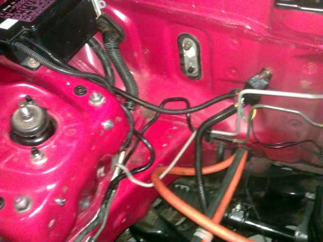
The cut and filed down battery box hangers (paint coming):
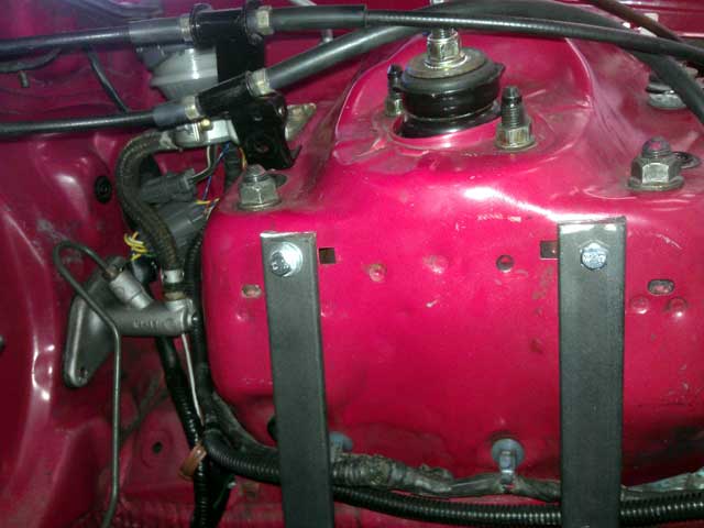
And finally the cut pieces off the hangers:
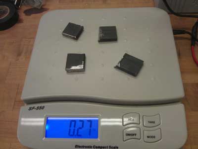
.27lbs saved! I will now search the entire car for extended
threads on bolts to trim off.
And I am, of course, JOKING! Although this seems possible albeit not probable. I have been questioning myself as of late!
Posted: Wed Dec 11th, 2013 04:12 pm
Well,
I won't even be happy with the battery box being so heavy. Come to find
out aluminum was 1/3 of the weight of steel. I had thought at least
half. So I ordered another battery box out of 3/16" 6061 Aluminum. I
caught the shop on a good day and so it may even be done tomorrow.
I
am going to buy a table saw and attempt to cut the battery box down for
under the hood. I think with a good blade, a lot of patience, and tape
I can cut the box down 1/4" without to much damage to the bedliner. And
if that doesn't go well I will just re-spray the edge's.
I have a list of 7 things I want to do on the car and 2 of
them got done today.
Still to do:
Prime and paint underhood battery rack and hangers.
Cut down underhood battery box 1/4"
Replace Airbag clockspring.
Secure interior battery box with another bolt.
Make new false bottom out of corrugated plastic for the interior battery box.
Posted: Thu Dec 12th, 2013 02:35 pm
Pleasant
with the progress today. I forgot 2 more things to add to my "list".
Mount the charger off the trunk wall and into the spare tire well. This
shaved 5.3lbs because I had the charger mounted on porch decking. I
extended the charger enable wire 5ft and mocked up where to mount the
charger before I go drilling holes into the sheetmetal.
I
also got the new battery box! It weighs 19.2lbs and is perfect. I had
it sized to allow a false back, sides and bottom. I will outline what I
am doing with that in the future.
The old crate I had the batteries in along with the moving blanket to not scratch the metal was a total of 15.8lbs. So this along with the charger decking makes it a total wash on weight!
Posted: Thu Dec 12th, 2013 10:28 pm
After
researching quality metal cutting saw blades and found they go for
twice the price of the used table saw I found, I began losing interest.
Since
it is only one small corner that need needed trimmed I opted to file it
down and touch it up with permanent marker. The option is still open in
the future to cut the whole battery box down but this may be good for
now. I hate doing that, but that's that.
To
mount the box in the trunk I need to hammer down a sheet metal rise (I
hate doing that as well). The only other way would be to cut the rise
out and then weld in a flat piece of metal which is even more invasive.
This rise is preventing the battery box from going up against the wall
in the trunk with the two holes I am going to help secure it. Normally
I could step it off with metal collars but since the battery box is so
heavy I want to use as short of a bolt as necessary. The longer the
bolt is the more chance of bad things happening with torsional loads,
as the box flexs going over bumps, and thermal events, etc.
Now
regarding the front LED signals. The turn signal circuit is bright but
when the low circuit is on because of the parking lamp (headlights on)
the turn signal is nearly indistinguishable. So I don't know how legal
it is but the solution would be to either disconnect the parking lamp
circuit, cover it with electrical tape/paint or not drive the car at
night.
Either way I will be required to add another resistor to the
turn signal relay, wahoo!
Ugg. I am doing things that are outside my norm of being
meticulous and detail oriented. I hope this doesn't bite me.
Added to the day is another problem with the website FTP server preventing me from uploading some nice pictures of todays events.
Posted: Fri Dec 13th, 2013 11:57 am
Pictures from a couple days ago.
The charger laid out in the trunk well:
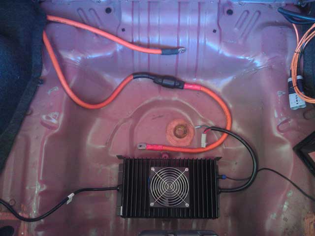
"Old" steel box with batteries and new aluminum one:

Plastic used to make false side, back and bottom pieces:
![]()
And finally the box in position:
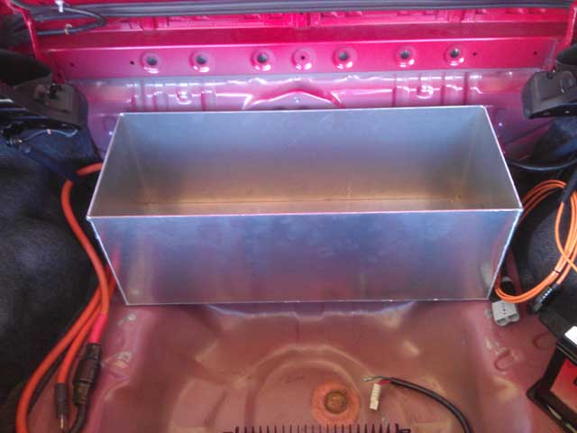
I
took a large ball peen hammer and flattened out the rise in the trunk
with much success today. The box now fits flush against the trunk wall.
And
I might as well tell everyone what I had "planned" that was in the
works. I am beginning to think neither one will become a reality so I
might as well tell you. First being the application for California
White Carpool lane stickers. I had looked on the application form and
saw a check mark for "Conversions" but that is for corporations or
business's that have filed with ARB (Air Resource Board).
The other thing which is not totally shot down yet but I am not holding much hope. There is a exhaust manufacture that has a R&D facility 1000ft from my house. Along with that is a Dynojet DYNO! I have known them for years and have many dealings with them. I sent a e-mail to them stating I know testing an electric car Is sort of a conflict of interest but would appreciate some help. Luckily it wasn't the electric car aspect that was preventing me from getting the Del Sol on the dyno. This is a busy time of year for them getting new applications designed and manufactured.
Posted: Sat Dec 14th, 2013 09:19 pm
I
found the time to replace the drivers airbag clock spring behind the
steering wheel. I was able to "center" the spring by feel before
installation and hope the one holds!
I also
primed half of the metal parts for the under hood battery rack with
acid etch. Tomorrow will be the rest and maybe paint Monday.
And
I officially went all OCD on the under hood wiring again and cleaned it
up even more. I really need to step away from this...
Clock spring replacement:
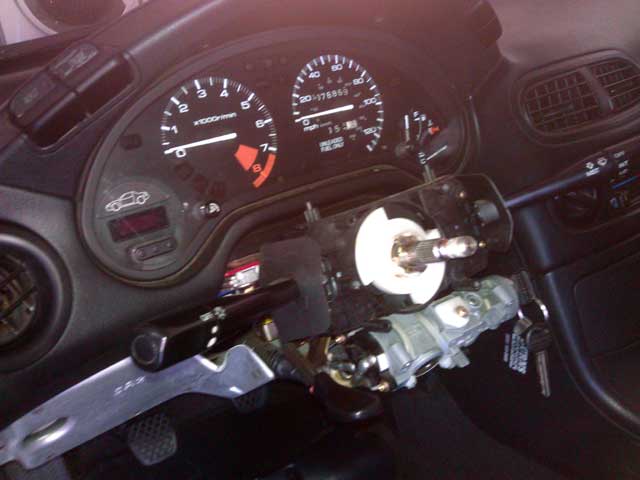
Wiring cleanup:
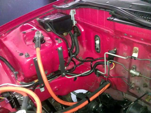
Posted: Tue Dec 17th, 2013 09:12 pm
I
put a piece of electrical tape over one of the connections on the front
turn signal to eliminate the parking light and it works great! I do
still have to address the rapid signaling rate in the future.
I also have the trunk sheet metal hammered as flat as I can for the rear battery box. The only thing I have left to do is acid etch the underside of the car where the paint flaked off. And then I will paint the underside "flat black" in that area
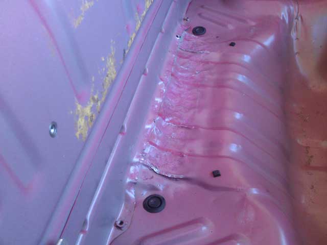
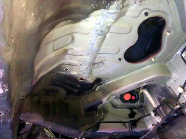
I am also in the middle of painting the under hood battery rack components
Posted: Wed Dec 18th, 2013 05:42 pm
I
went to the local Autozone to buy more of the aerosol can spray on
bedliner to at least give the underside of the car a little protection
from that bare metal. Not wanting to mix up another batch of the 2 part
bedliner I apply with an air compressor, there would be a lot left
over. I was happy to find a paint on bedliner that can be applied with
a standard brush!
Happy with this
development I went crazy acid etching the underside of the car where
the gas tank was. I have more touch up work to do before I apply the
bedliner but with rain expected tomorrow that may get delayed. I am
also debating coating the tunnel where the exhaust was routed to
further reduce any noise.
The bedliner:
Acid etched underside:
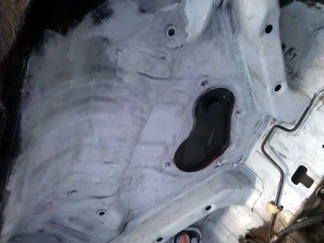
Posted: Sun Dec 22nd, 2013 05:51 pm
Another 1W resistor was added to the turn signal relay and now
the signals flash at a normal rate of 1 flash per .8-.9 second.
One coat of bed liner was put under the rear of the car, still
1 coat to go.
The underhood battery rack and hangers are painted and awaiting installation.
Posted: Fri Dec 27th, 2013 05:13 pm
Just an update:
The bedliner under the rear of the car is complete.
The underhood rack is painted and installed with the battery
box.
Everything
on my little "wish list" is complete with the except of mounting the
charger and battery box. Oh yeah and coating the box in bedliner.
The weight savings going from porch decking to corrugated was 7lbs. Every little bit counts. That's almost the weight of 1 battery (7.5lbs).
Posted: Sun Dec 29th, 2013 07:34 pm
Bedliner complete:
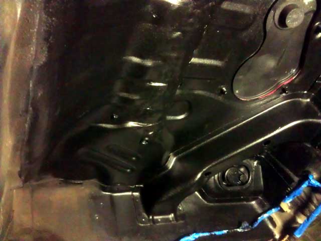
Battery box trunk wall bolts:
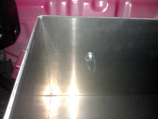
Posted: Tue Dec 31st, 2013 07:10 pm
Painted underhood battery rack:
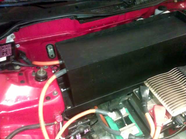
Trunk wall spacer for battery box:
![]()
Simple 3/4" nylon spacer. I used nylon on purpose. Though the
exact reasoning is not worth trying to decipher.
Trunk floor spacer for battery box:
![]()
Consisting
of 2x 2" fine threaded bolts with a steel sleeve/collar with a washer
on both ends to distribute the load more evenly. The steel sheet metal
of the car will go between the lower washer and the nut.
With
no real example or direction like much of this project, just using what
I feel is sufficient at the local LOWES. I couldn't find a NYLOCK nut
so the "make do" is RED Loctite and an obscene amount of torque!
In
other news please reference the photo posted on Dec 13th in this post
with the 2 battery boxes on the ground. I had incorrectly put the
batterys in the box facing front to back. So 5 wide and 4 deep. When I
saw this extra space I tightened up the tolerances when I had the
aluminum box made to replace the heavy steel one.
Then
I go to test fit the batterys in this new box in the trunk and oddly
enough I had 2 batterys left over! Yeah, I had made the steel box 1
inch wider because I was going to run 2 strings of 11 batterys facing
each other sideways. I guess I will just chalk this up as unforeseen
overages. Which by my rough calculations are @ $1000.00 for the project.
So now the magical battery count will be @ 59 unless I can find somewhere convenient to mount 2 batterys.
Posted: Thu Jan 2nd, 2014 12:16 pm
So,
it turns out I measured thought the layout of the battery's was
incorrect from the beginning. It turns out the original steel box was
the same dimensions except a half an inch shorter. When I felt how
heavy the box was I decided right there to get it made in aluminum. I
didn't test fit the battery's at all.
I am trying to find other areas to stuff the 2 remainder battery's.
Posted: Fri Jan 3rd, 2014 10:01 pm
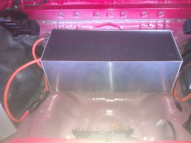
The
trunk battery box is in and secured. It is however, naked. I decided
against coating it. Mainly because it would have thrown off the
tolerances on all the bolt holes that I had pretty much exact, it's in
the trunk and unseen, and I like the brushed look!
I
made a 2 inch wide strip of decking to cover the two bolt heads in the
rear floor of the box. The rest of the area I covered with corrugated
plastic. It's about an 1/8" inch lower the decking. I am not concerned.
One thing I did it cut the holes slightly smaller then the bolt heads.
I then hammered it onto the decking. The decking formed around the bolt
head perfectly. This will come in handy to trying to secure the nuts
while under the car.
But the box is in and
secured and looks great. I am going to forgo the installation of any
more bolts in the box because I believe it to be secured enough. As
luck would have it the box edge is mounted right next to the centerline
from rear strut tower to strut tower. Why is this important? Well if
the box staying secure becomes an issue, I can run a strut tower brace
from side to side to help hold it in place. These braces are going for
a cheap $30-40.00 on Ebay. And if I had the box made for those 2
additional batteries it wouldn't have worked. Funny the way things work
out. I still would have rather had the 2 batteries.
I need to hook the battery straps up and secure the charger in the trunk. Then I will begin to bottom balance.
Posted: Sat Jan 4th, 2014 02:54 pm
The
front and rear battery boxes are hooked up with connections. I have
also begun bottom balancing the batteries. The first 2 batteries have
taken 70 minutes and removed 32-33AH. Need less to say this may take a
while.
I installed more carpeting in the trunk. I marked where I need to drill for the battery charger. Just exhausting all other ideas on mounting it before I start drilling into sheet metal!
Posted: Sat Jan 4th, 2014 11:40 pm
It's late, and I may find a reason for this in the morning but
here it is.
I
find it odd that between 32-33AH are being removed from these
battery's. After all, I under charge then to 3.5v which means they are
not filled to capacity, and I rarely going beyond 50% depth of
discharge (DOD). I checked the JLD404 meter inside that car that was
never reset since the last full charge. The meter reads 96.6AH removed
from the pack.
I think the meter is not
reading the usage correctly. I will verify the settings tomorrow.
Thankfully its erroring on the side of caution rather then more actual
usage then displayed.
I am @ battery number 9 at the moment.
Posted: Sun Jan 5th, 2014 02:25 pm
I
changed the charger curve to the 208.8v #6 selection. This will give a
cell voltage of 3.538v per cell. I also set the JLD404 meter to kill
the enable signal @ 209v if the charger goes on the fritz.
And
yes the instrumentation of the JLD404 meter is off. I am starting the
discharge @ 3.27v per cell. Which is much higher then the 3.10v or less
it should have been after an indicated 96.6AH removed.
The
most obvious thing would be a 1000A shunt selected for an actual 750A
one. I will check on all this in the future. I guess I could just
recharge the car near the 100AH indicated on the meter rather then
70AH. But it really would be nice to have an accurate reading.
Because I had planned to run 2 strings of batteries in the trunk I had straps ordered to mount the batteries face to face. Now with running them end-to-end that throws off my count since they are sized smaller for mounting sideways. That means ordering 6 more smaller side to side straps from EVTV. It also means 3-4 days shipping but that's ok judging by my bottom balancing progression rate
Posted: Mon Jan 6th, 2014 10:37 pm
7 more short 60mm straps are ordered from EVTV. They should be
here Thursday.
I am currently on battery #25 of (at this point) 59. I am doing the initial drain to 2.5v and having them battery's bounce back to 2.85-2.90v. I will do the second cycle of draining to 2.75v once all the battery's are hooked up and I can immediately start the charge.
Posted: Tue Jan 7th, 2014 08:22 pm
On battery #35. Both front and rear battery boxes are complete. The final remaining 24 batteries are in the car behind the seats. I need the battery straps to complete this. I may end up putting a terminal on each battery just to drain it.
Posted: Wed Jan 8th, 2014 09:36 pm
Well
that's consistent. Today I finished at battery #47. The last 12 will be
drained tomorrow. Then allow 24hrs to settle and a final drain to 2.75v
before the first initial charge. No big surprises so far. I am guessing
this time around there will be less of an initial sag in voltage after
a recharge because the battery's will be more precisely balanced.
Your battery pack is only as strong as its weakest battery. Meaning if you have a battery cell that is .05v lower then the rest, all your batterys will be at that .05v lower level. Multiply that 59 times and that's 2.95v. Almost an entire cell lower.
Posted: Fri Jan 10th, 2014 01:05 pm
The
first pass of bottom balancing concluded without incident. The battery
final battery straps are supposed to be here today. As soon as that
happens I will lightly sand clean the battery terminals, strap the
battery's together, bottom balance the second pass which should take
2-3min per battery and the 20KW of power from the 2500watt charger.
Yes, 8 hours of charging for this initial charge.
Glad to be on the weekend rate schedule with the power company when that happens.
Posted: Sun Jan 12th, 2014 05:36 am
After 17 1/2 hours straight in the garage from Noon on Saturday until 5:30am Sunday morning the batteries are balanced and charging. For some idiotic idea I decided to balance the battery's to within a thousandth! It's going to charge most of the day.
Posted: Sun Jan 12th, 2014 05:52 pm
OK
initial reactions. The initial additional acceleration I used to feel
for the first mile or so goes on much longer. What I used to feel was
either the additional surface charge wearing off or a imbalanced pack
sagging. Whatever the case may be I like the improvements a lot.
You
know what I find better then the battery upgrade? The bedliner under
the car! It has really quieted down the cabin of the car. Gone are the
sounds of little pebbles and rocks hitting under the car where the gas
tank was. I am glad I did this.
So now what?
Well
for now I am just going to enjoy having the car again for a while. Then
I need to figure out the charger situation. Am I going to just use this
2500 watt model or double up and get another identical model.
12v
power, am I going to run a 12v alternator of the tailshaft of the motor
along with the A/C compressor? Or just use a DC/DC convertor. Or keep
things as they are and add a solar panel to the rear decklid to keep
the 12v battery charged.
At this point I am leaning towards a small 12v motorcycle battery to engage the DC/DC convertor which will then in turn be recharged via small circuit back to the battery once the DC/DC is turned on.
Posted: Mon Jan 13th, 2014 01:49 pm
OK just going off the top of my head, I have some numbers.
First
I found a nice 10.5mile 13AH (indicated) control loop I can use for
testing. There is very little cross traffic so I think that will do
nicely.
I drove 58 miles today concurrently
for a 82AH (indicated) removed from the pack today. I am going to wait
and see if the voltage creeps back up from the 3.19v per cell. Remember
when I was bottom balancing the cells and found 32AH could be removed
from all the cells when the JLD404 meter had indicated 96AH where
removed from the pack. The measured voltage before those 32AH where
removed was 3.27v per cell. So there is some promise there.
As
I was driving around with the nice quiet cabin I could hear that
mysterious clicking sound under 20-30% throttle more distinctively! I
then happen to look down at the JLD404 meter and could see the LED for
the J2 relay control lighting up and going off with the clicking sound!
I looked at the JLD404 J2 menu and I had it set to AMPS and the AH2
setting at 200 and the AL2 setting at 100. So it was clicking on at
200AMP and then back off at 100AMP. I have no idea what that was
originally set up to do. My guess it was just something I was playing
around with at one time and never cleared the settings after I was done.
This is great news because that relay control uses 1.**AMPS if I recall correctly.
Posted: Tue Jan 14th, 2014 07:15 pm
The
cells finally settled @ 3.07v per battery. And when I recharged the
pack the JLD404 meter was only off by a tenth of an amp. Hmmmm
Questions, Questions, Questions. Did I do a partial recharge on that
last day before taking the car apart, I must have. Because to have
3.27v left in the cell with 96AH removed is hard to believe at this
point unless something else presents itself.
So as the car sits now it is a 70mile range car. That's if I do a 70% discharge. That falls 5 short of my goal, but I am confident in the weeks ahead improvements will be made.
Posted: Sun Jan 19th, 2014 09:05 pm
A new "to do" list.
Get
shorter front battery box to shunt cable with correct sized lugs on
each end. The current cable is 20inches to long and has a larger hole
on the battery pack termination lug.
Relocate Soliton1 and water pump ground to a more hidden
location.
Shorten coolant hose from the Soliton1 to the water pump.
Mount battery charger in trunk.
Cut and mount carpet in the trunk that goes on the back wall
behind the battery box.
12v power solution as listed a few posts back.
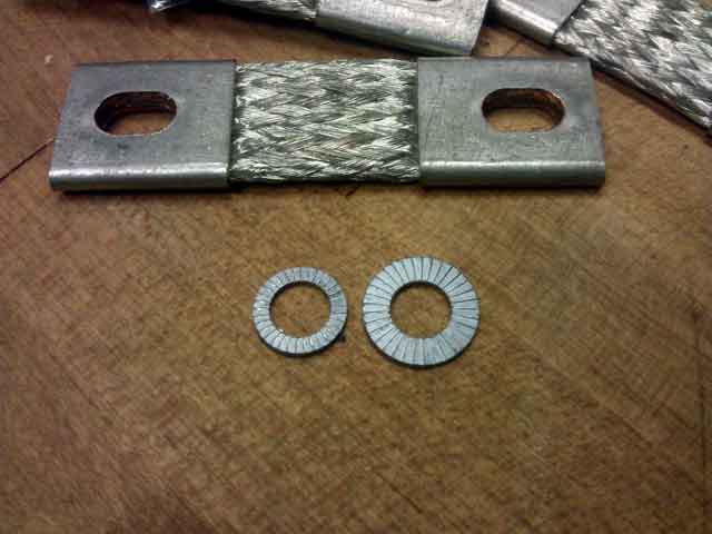
I
noticed in my latest shipment of battery straps that EVTV is now
including LARGER NORDLOCK fastener washers. This provides a larger
surface area for the connection. Kudos to EVTV for making this running
revision. I did not see mention of it anywhere. I now have these larger
washers on the front and rear battery box. I don't have enough for the
interior box.
I put about 100 miles on the car this weekend.
Posted: Wed Jan 22nd, 2014 06:32 pm
The
charger has been mounted in the trunk floor. I only utilized 2 mounting
holes because I left the option open to then mount the charger upright
instead of flat and add an additional charger next to it.
The
charger now runs cooler by having all that metal of the trunk to act as
a heatsink. 2 times now I have forgotten to unwrap the charger from the
moving blanket I had it wrapped in when recharging. Luckily the charger
derates because of heat and prevented a fire.
I also routed the ground wires for a cleaner look
Posted: Tue Jan 28th, 2014 04:39 pm
I don't know if someone is looking out for me or people are
just being nice.
Yesterday
I got a flat tire on the front right side. It was quickly removed and
patched up free of charge thanks to a local Discount Tire less the a
1/4 mile from my house! Free do to his interest in the car and the fact
that I had brought it there for the past alignment.
Today
I went to Radio Shack looking for a rocker switch to turn the JLD404
meter on/off. I quickly met 2 nice people behind the counter and told
them what I was looking to use it for. Before I bought the switch they
asked to see the car. After about 10 minutes of talking we went back
inside and I picked up the switch still on the counter to pay for it.
Then they said to take it free of charge! It was only a $5 switch but I
thought that was kind of cool. And luckily one of them was a manager so
it didn't cost anyone their job.
I will
mount that switch up soon. It's a "double pole" switch so I can switch
another circuit on the other connection of the switch.
I
ordered 80 of the larger NORDLOCK washers from EVTV to complete
converting all the battery strap connections to this improved method.
The miles just keep on racking up. Of course with the car being back together this will happen more and more. Today marked 5,000 electric miles on the car. Eventually this to will become less noticed or tracked as time goes on.
Posted: Wed Jan 29th, 2014 09:23 pm
I wired up that switch to turn the JLD404 meter on/off. I put
the switch on the drivers side of the center console.
I also took off the plastic front air dam cover AGAIN, because basically I am indecisive as all hell.
Posted: Mon Feb 3rd, 2014 05:56 pm
Replaced all the washers on the battery straps with the wider NORDLOCK ones.
Posted: Wed Feb 5th, 2014 09:03 pm
The
coolest thing happened tonight. I frequent a local gas station for
energy drinks every week in the area. Over the years I have gotten to
know the people. One of the employees is taking a class at the local
"Saddleback College" for automotive. When he told the instructor about
the Del Sol he kept hounding me to stop by the shop and show the
instructor and class.
I finally bit the
bullet and headed down there tonight. I spent 1 1/2 hours talking to
the class and answering questions. They had a "OEM" electric vehicle
there from a Korean company called "Taurus" that they had bought for
$4000.00 and was limited to 25MPH using 6volt AGM batterys. Everyone in
the class said how professional the Del Sol looked compared to the
"OEM" car. I was also invited to a couple field trips they have coming
up to state run laboratories investigating alternative fuels.
The whole experience was awesome and I am glad I went. I was treated very well by everyone involved. I was also given a open invitation to use the 8 bay shop for any repair I needed to do on any car!
Posted: Fri Feb 7th, 2014 11:43 am
I
found a "semi local" event I would LOVE to attend! Even if I do make it
up there without recharging I would be worried about not finding space
a recharge for the trip home.
I like that it is for all electric cars only, this is what it should be for. Not for cars that use "a little less" gas. For cars that use NO GAS! I am trying not to be stuck up here but even people driving PHEV's claiming to drive "all electric" irks me.
Posted: Mon Feb 10th, 2014 10:40 pm
In yet another example of awesomeness, I have come across a nearly endless supply of used 18650 lithium ion battery cells. These are batterys from laptops and cordless power tools. No idea what I am going to do with these. If anything I will experiment on making a 36v pack for an electric scooter that is sitting in the garage. If that goes well I have a more long term plan of creating a 12v battery to turn on a DC/DC converter. Then it will recharge from the converter. The battery circuit will have a diode so the little 12v battery pack doesn't try powering the entire 12v system in the car.
Posted: Sat Feb 15th, 2014 05:43 pm
Other things are occupying my free time at the moment.
All those 18650 battery cells I am getting are coming in around 1600Mah according to the Powerlab8, so not sure what to do with that. I think I am going to build a 36v pack for my scooter and get a 10ah 12v lithium battery off the EVTV website for the car. All of which is unnecessary until I get an Elcon DC/DC convertor from EVWEST.
Posted: Sun Apr 6th, 2014 04:31 pm
I
am back after 5 weeks away. I "broke" all 3 battery packs by removing a
connecting strap to the batteries while I was gone. I also left the
pack discharged 50% for storage. This is the way the cells come from
China and if you look at the charge curve, its a great place to keep
them for longevity.
Hooked everything back up and everything is as it should be,
just in time for increased gasoline prices!
I will be finishing some things off in the upcoming weeks on the car.
Posted: Mon Apr 14th, 2014 01:51 pm
Random mileage update. Car now has 6,000 miles since being converted to electric power.
Posted: Tue Apr 15th, 2014 04:29 pm
I
had the chance to take the car on a contiguous 38mile trip today.
Through a local canyon by a state wilderness park and lots of twisties!
While I didn't "push" the car to hard I am happy with its handling. In
typical FWD fashion it wants to oversteer.
At the end of the trip I had consumed 43AH from the pack. So this does sound like a safe 60-75mile range car with 70% discharge
Posted: Mon Apr 21st, 2014 08:18 pm
I
generally detest stickers on cars. In fact it wasn't until 5 years ago
that I started putting a single choice sticker on a vehicle.
When I saw this I had to buy it for the Del Sol! Even at the risk of looking a little braggy.
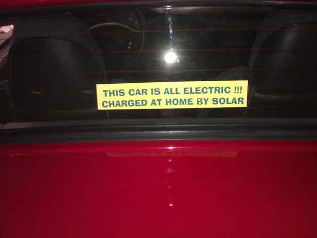
Posted: Mon Apr 21st, 2014 09:29 pm
LOL, as someone pointed out on a TESLA message board "Usage"
is spelled wrong. Even I didn't notice this at first, wow!
I am just going to "chop" off the last line with a razor!
Posted: Thu Apr 24th, 2014 03:54 pm
The push for a higher charging rate.
I
can only cite 1-2 instances where the battery charge was down to low to
recharge in enough time to make a lengthy trip. So does a 2.5KW (2500
watt) charger really make sense? For me it does, for many it won't.
Allow
me to elaborate. I am still in the Winter billing cycle with my
electricity provider (SCE). During this time peak rates are between the
hours of 12-6PM. As it stands at the moment there is only a single hour
out of that time when the solar panels on my house will not 100% offset
the car charger. That is the hour between 5-6PM.
This will shift as the Summer billing rates change over, how
much remains to be seen.
If
I used public charging that charges for the time I am charging it would
make sense to charge as quickly as possible. But as it sits right now I
am charging at home.
Things can and will change in the future.
Posted: Sat Apr 26th, 2014 11:19 am
I have other things STILL taking up my time. No end is in sight
Posted: Tue May 13th, 2014 11:39 am
As an update I returned after a 2 week trip across the states. I had "split" the pack again by removing one terminal in all three of the battery packs. I have resumed daily driving of the Del Sol.
Posted: Fri May 23rd, 2014 10:16 pm
Continuing
to drive the car daily. I am accruing miles at the rate of about 50 a
day. I got the question twice today from different people what I would
do differently if I had to convert the same car again.
I
thought about it and just off the top of my head I would.....use an A/C
motor rather then D/C, use 108-144v 500Amp controller, use 33-45
batteries rather then the 59 and some other minor things.
But I wouldn't trade this experience for anything in the world! I am happy with the car as it sits. I have allot of things planned in my personal life that takes me away from the car. But in the meantime I am glad to have the car complete enough to be driving it around and showing people.
Posted: Fri Jun 20th, 2014 04:47 pm
Another
thing I have been doing to delay the inevitable is to "blow out" the
motor around the brushes and fan with compressed air to remove carbon
build up. This is in place of buying a fan for the motor and hooking up
the temperature control in the car that's already fitted. Blowing this
carbon dust out is crucial to avoid a "flashover" situation where high
voltage essentially arcs across the surface. When I did this today I
noticed more carbon dust come out then usual. This doesn't really mean
much other then a fan will be required in the future.
It would be great to find a weekend where I could just get all
this stuff hammered out that is still looming.
The car is at 7,000 miles since conversion. Thats averaging out to about 500 a month since my last update. Less then expected at the moment
Posted: Sat Jul 5th, 2014 12:19 pm
To
extended the 12v battery and eventually draw less power from a DC/DC
converter I am purchasing a set of Philips HID headlights. I have dealt
with the Philips brand before and they have been flawless. A couple
years ago I took advice from a friend and purchased a MTEC HID kit off
Ebay for my Mercedes, but had NOTHING but problems with it. I had gone
through 2 ballasts and 1 bulb in a year. So back to the trusted Philips
brand. These are the new slim style ballasts that are much smaller then
the Philips LVQ ballasts from 8 years ago.
Each
headlight draws 20A right now and that is set to be reduced
significantly. Check out this video on YouTube to see what I am trying
to convey: http://youtu.be/NCqjSLUIkjk
And the actual kit I am buying is located here: http://www.philipshidkits.com/h4-bi-xenon-philips-slim-ballast-hid-conversion-kits/
I will test this to see how lasting of a solution this will be for night time driving.
Posted: Fri Aug 1st, 2014 05:34 am
Not
to leave everyone in suspense.....other exciting but non car related
activities have kept me busy. I received the new HID lights but haven't
installed them yet.
I am also going forward with a small lithium 12v auxiliary battery purchase as well as a small 35A DC/DC converter. This is electrically isolated so another converter can be added on top of that, if need be. This change, while adding the comfortable ability to drive at night will also remove 25lbs from the original 12v lead battery even with the added component, which is always welcomed. All in due time I suppose......
Posted: Sun Aug 10th, 2014 02:52 pm
Minor
error on my part. I thought I was "under driving" the headlamps by
replacing the fuse with a lower rating. It turns out they draw much
less then I had originally thought possible.
As I convert the headlights to HID I decided to take some measurements to see what improvements I would be making. As it turns out the stock 55w Halogen bulbs draw 3.48a if I am doing this correctly. This is 3.7a load on a single headlight fuse with a battery voltage of 12.9v. So lets see what the HID lights measure!
Posted: Fri Aug 15th, 2014 08:35 am
A local event celebrating "National Drive Electric week". I
will be there!
https://driveelectricweek.org/event.php?eventid=158
Posted: Mon Aug 18th, 2014 07:13 pm
There
is no easy way of measuring the current draw of the new HID headlights.
I saw written on the HID ballast a current draw of 3.2A. However the
kit included a secondary wire harness to boost the higher initial
current draw of the HID ballast firing up. That harness has a 30A fuse.
Either
way I have been busy with other things to complete this in a timely
manner. I will get some measurements of the completed circuit.
And if I told you the personal things going on in my life that is taking me away from this task, you would NEVER believe me.
Posted: Thu Aug 21st, 2014 11:14 am
As it would turn out things are not looking promising on the
"energy saving" front with regards to the HID headlights.
The
HID headlights draw the same 3.78A through the OEM Honda harness. Then
draw the exact same 3.78A through the auxiliary harness included with
the HID kit!
This from a ballast with a Max 3.2A rating?
Yeah, and of course the lights are very bright.
Stay tuned....
Posted: Thu Aug 21st, 2014 08:49 pm
OK,
after hooking up both HID lights they still pull the same 3.78A through
the auxiliary harness and 3.78A through EACH one of the individual OEM
headlamp fuses (LEFT and RIGHT).

Posted: Sat Aug 23rd, 2014 10:26 am
I
did some napkin math and took AMP readings at the 12v accessory fuse
block underhood. I figure 18A would be a typical load with the
headlights on at night and the coolant pump on to cool the controller.
So I am going to try and use a 400watt 30A DC/DC converter for the
meantime. With the understanding I will be adding a contactor as a
failsafe to the circuit.
This is without the radio, HVAC fan running. But by having a overload protection built in to the DC/DC I can be in the garage and keep turning items on until I find the breaking point. And at that point add another one.
Posted: Wed Aug 27th, 2014 10:58 pm
Some random pictures.
Previous wiring layout with NO contactor.
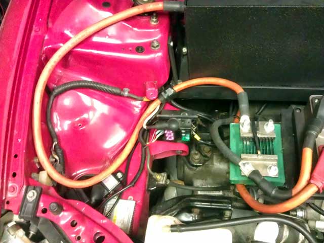
Fabricated contactor mount using flat stock. Then used existing mounts for factory airbox to mount.
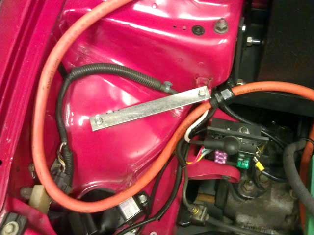
Contactor mounted and all but 1 wire connected.
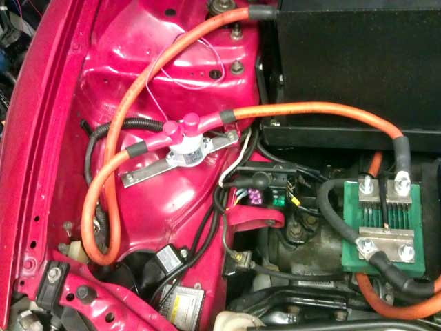
Unmounted DC to DC convertor.
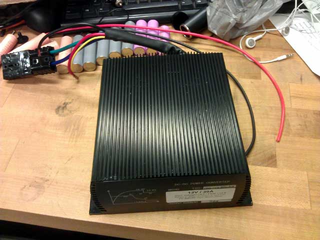
Posted: Thu Aug 28th, 2014 03:53 pm
I
am out of space under the hood for components. Well, not really but
short of fabricating up a weird mount to mount this DC/DC converter off
the battery box, nowhere is going to look "clean".
In
the trunk I had a pigtail created on the charge cable to add an
additional charger. For now I am going to "borrow" that connection and
run the DC/DC in the trunk. Temporary mounted on the top of the rear
battery box. I am using the same porch decking I had used to mount the
battery charger the same way. This is a temporary solution.
And yes, its another case of having to many things on my mind. I failed to realize I am now going to have to have the ignition switch on to charge the car. The solution is to move the contactor enable wire to the switch in the center console for the JLD404 meter. Which is great because this also means I cannot charge or run the car without the JLD404 running to keep track of my energy use.
Posted: Fri Aug 29th, 2014 07:42 pm
I
have everything hooked up. The DC/DC is working nicely. One problem
however. I am not accruing usage on the JLD404 meter when its on and
the headlights are on. This baffles me a bit because I am DRAWING power
from the same power cable that the charger is SUPPLYING power to charge
the batteries. And that cable is hooked up on the load/motor side of
the shunt.
It's a minor issue I do need to solve. Based on my napkin math and observing 15 minutes of usage vs what t takes to recharge the pack I figure I use 1.5AH of pack use per hour with the DC/DC converter on. In the meantime I wont drain the battery pack to close until I get that fixed.
Posted: Fri Aug 29th, 2014 09:33 pm
Good news. It is accurate. The power draw is so low it takes
me turning on quite a few items for it to register, but it does!
Since
the power draw is so slight under light 12v load, I wonder how "off"
the JLD404 meter will be when I recharge. Only time will tell.
And I am glad to have this solved. I would have wondered about it all night
Posted: Sat Aug 30th, 2014 09:58 am
That
didn't last long. With a couple hours to spare this morning I moved the
contactor enable wire to the JLD404 switch. Much better.
I drove around this morning as usual but with the headlights and HVAC interior fan motor on low. No problems as of yet!
Posted: Sat Aug 30th, 2014 09:21 pm
On
my 1st recharge of the day the JLD404 meter still registered that I had
6.0AH left to "put in" the pack when it hit my 200v charge limit and
cut off. On a hunch I drain the pack down to a similar level. I then
disconnected the DC/DC converter and charged as usual. This time it was
off by .7AH. This is the accepted norm. It has never been spot on.
So
what does this tell me? It tells me that I cannot have the DC/DC
converter on while recharging. For whatever reason it doesn't allow the
JLD404 to accurately keep account of the AH.
It's
purely psychological. As the JLD404 meter kills the charger enable
signal when it reaches 200v anynow. But I do want accurate information.
As I find time this week I plan to rewire the contactor under
the hood and once again try and find a place for the DC/DC.
I know I am going to need at least a 18inch battery cable from EVWEST. This will make the 4th trip down there in the past week. Mostly involving "other" things
Posted: Mon Sep 1st, 2014 08:03 pm
Another day, another revision!
I
decided engaging a contactor to recharge is not the way to go. Because
by doing this, ideally I would also need to enable the DC/DC converter.
That .3amp holding current of the contacter would eventually drain a
battery. Especially as I go to the small 12v lithium battery to replace
the lead 12v car battery.
So I need another 18" long battery cable terminated at both ends with 1/2" lugs. Then I need to move the DC/DC converter under the hood and have the engagement point after the contactor. Speaking of which, I think I found a place for the DC/DC. I am going to try and mount it on the underside of the front battery framework. It's actually a pretty nice place if I can make it work. And the aluminum frame makes a nice heat sink.
Posted: Tue Sep 2nd, 2014 01:12 pm
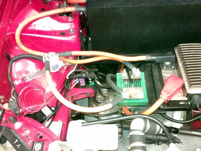
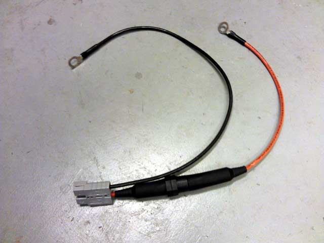
EVWEST
did an excellent job making another battery cable. They also made a new
DC/DC cable with a smaller Anderson connector and used a spare set of
wires I had made up earlier in the conversion that had ring terminals
for the Soliton1 controller. I think I use to charge the batterys at
one point when I had the charger mounted briefly underhood.
I
am going to try and mount the DC/DC on the front battery rack without
removing the rack. I will find a good place to mount it and lay the
DC/DC on top of the rack with the battery box removed and mark the spot
to drill with a hole punch. Then if all goes well I will drill the
holes and flip the DC/DC upside down and mount it under the rack.
EVWEST also made the DC/DC power cable with an inline fuse which I like alot better then wiring it up to a high current fuse block (which they already sold me) on the firewall. I will return those at some point
Posted: Thu Sep 4th, 2014 06:02 pm
All back together! It's charging and I will put miles on it tonight/tomorrow.
Posted: Fri Sep 5th, 2014 12:42 pm
The
car is great! Once I get more miles on it, I will feel better about
eliminating the big 38lb 12v lead battery and going with the 1.5lb
lithium 12v. Right now the battery is my emergency fallback. Like if
the DC/DC where to fail, I could drive home on the 12v. It's just a
buffer that I like to have right now. I will get over it eventually.
Which reminds me I need to order a diode from EVTV so that little 12v battery doesn't try and power the entire car, just the ignition circuit with the contactor for the DC/DC converter.
Posted: Sun Sep 7th, 2014 07:29 pm
As
luck (or lack thereof) would have it my DC/C converter has failed. It
blew a fuse yesterday and didn't come back online when I replaced it.
I
will leave out the sob story of walking home to get a replacement fuse
and then walking back to the car 2.0 miles away from home. Some turn to
alcohol, but I resorted to energy drinks and sweets to drown my sorrow
And my disassemble level of the front battery box has hit
expert level! The task was completed in 45 minutes.
I will see what EVWEST says tomorrow!
Posted: Mon Sep 8th, 2014 08:52 pm
I
went to EVWEST today. They quickly determined the DC converter was bad
and warrantied it on the spot. They also put in a Diode to prevent
problems in the future. Unknown the specifics on its purpose. I know
Jack Rickard from EVTV recommends something similar. I think on DC
motors it is prone to surges/spikes from backflushing after full
throttle application.
A big thank you to
Matt Hauber from EVWEST who took timeout of his busy schedule to solder
up the diode and redo the DC converter with Anderson connectors for my
hookups already on the car. They had a million things going on so for
him to take this time was a big deal.
Interestingly enough the new DC converter does without the
Yellow wire. This must be a running change that Elcon instituted.
I will drive the car all day tomorrow to test it out
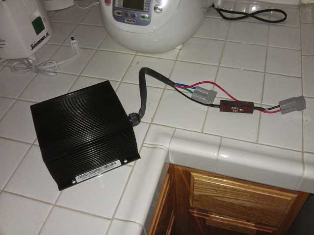
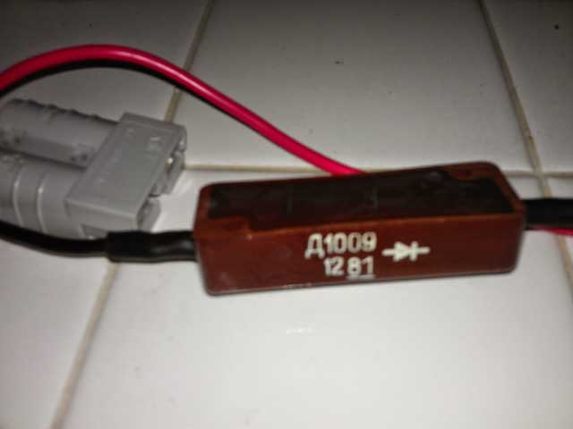
Posted: Tue Sep 9th, 2014 03:12 pm
Presumed success! I drove the car around all day. I slowly
ramped up acceleration until I felt comfortable everything was "ok".
The
local EV car show event was pushed back 6 days to a Sunday instead of a
Tuesday. I don't know why this wasn't done sooner! This is a much
better time!
Details of the EV car show in Southern California is located @ https://driveelectricweek.org/event.php?eventid=158
Posted: Sat Sep 13th, 2014 04:16 pm
Yes,
indeed everything is fixed. I have been using the car for about 50
miles a day, with headlight use at least half of the time.
The
only thing that has come up is this warm weather the past week! Not
having A/C is bothersome to passengers but I live with it. So on the
back-burner is the notion of getting a A/C compressor plate made to
attach to the Warp9 motor auxiliary shaft. That is only part of the
issue as I will have to relocate the Soliton1 cooling pump and find a
A/C hard line solition. I don't think the original hard lines are going
to work with the battery box mounted where it is.
I think its alot of trouble for what I consider a negligible gain. In a few weeks its going to turn cooler. Then the issue may be to have a working A/C compressor for the defrost to function
Posted: Sun Sep 14th, 2014 08:34 pm
Spoke to soon. Although unrelated to previous occurrences, the
car died today after a full acceleration stint.
I
have an error on the Soliton1 controller. First the error was a
"precharge low voltage". I cleared the error with my laptop. Then the
error that came back was "Desaturation error". A quick and timely
response by EVNETICS tech support offered this depressing response to
the question " Is there anything that clear this error?".
<<<<<<<<<<<No,
sorry, this is a fatal error. Your motor has shorted, the controller
has failed, or both.
Evnetics
Support>>>>>>>>>>>>>>
Jack Rickard from EVTV had this to say in response to me
asking him "Has this ever happened to you?"
<<<<<<<<<Yes.
It required return to EVnetics to fix it actually.
Jack
Rickard>>>>>>>>>>>>>
ACK! And a week before the car show I wanted to attend.
I have a few solutions in mind for the interim, we will see!
One interesting point to note. Today I drove the car in the hottest weather I ever have. Unknown if there is a relation
Posted: Tue Sep 16th, 2014 07:12 pm
The controller is packed up and ready to ship tomorrow. No real rush at this point.
Posted: Thu Sep 18th, 2014 07:32 pm
I
forgot to backup my setting on the Soliton1 so I hooked up a fused
cable to that little 10ah lithium battery. Upon backing up the settings
through the web interface I noticed that the only error that came up
was a low voltage precharge timeout. This is because the high voltage
wires where not connected. Thinking AND hoping that the desaturation
error would have taken precedent over that error, I hooked it back up
in the car. No such luck, as the desaturation error came back. It was
worth a try. What I did find was a leak to ground. At this point I
would just say don't ask me how I know but I will just tell you. With
the contactor off but the pack not "split" I removed the positive wire
from the Soliton1 battery side. Well the 3/4 wrench spun around and
brushed against the metal case of the controller. An immediate shower
of sparks came about, OH THE HUMANITY! OK it wasn't Hindenburg bad but
you get the gist. This marked up the threads on the controller but I
was able to slowly back the nut off of the threads and then back on and
clean the threads, again and again until it came off without incident.
I guess I will ask EVNETICS how much a new terminal post would be along
with repairing whatever else is wrong with the controller.
I had some time this evening to try and track down that frame leak. I backtracked the battery cables through 2 of the 3 battery boxes and have not found it. I have a sneaking suspicion its the positive lead on the charger cable that leads to the trunk, but nothing concrete yet!
Posted: Sun Sep 21st, 2014 03:58 pm
I sucked it up and went to the car show EVless. Alot of TESLA's on display and a few Leaf's. I got to hear "I really wanted to see a homemade electric car" from people who saw I had registered beforehand! I guess I should probably get that controller in the mail....
Posted: Wed Oct 15th, 2014 04:49 pm
Yeah, so, its like that! Would you believe I got the Soliton1 controller off to FL for repair today? $80.00 in shipping later, its on its way.
Posted: Thu Oct 30th, 2014 04:21 pm
Your
all sick! Sick I say! Yes the lack of news has caused an influx of
visitors to this page. Perhaps fearing the car burned my house down
and/or caused me great bodily harm. Fear not however, this is not the
case! I have a large repair bill in hand from EVNETICS and I will call
again (missed them today) tomorrow and arrange payment. I will get into
the specifics of the repair bill at a later date but they are replacing
allot of hardware.
This when the gas prices
have dropped to the lowest they have been in 4 years. That's great and
all but the low gas prices still don't help the environment if you just
forget and go back to your old ways!
So many exciting things happening in the energy sector right
now.
I expect the repair and shipment of the controller to happen next week.
Posted: Mon Nov 3rd, 2014 12:47 pm
I
called EVNETICS again on Friday but did not receive a response. So one
of today's primary goal was to call and make payment. I called and it
went to voicemail. I then called back 2 times and Steve from sales
picked up the phone. He said Aymee was at lunch and she was the one to
talk with. I got the time she would be back from lunch and called back,
no answer.
I went into full redial mode! So for 45 minutes I called the number and would hang up on the ring before it goes to voicemail. She finally answered to which my statement was "What did I win?" she replied with confusion which at that point I reassured her I am much better at "annoying" then she could ever be at "ignoring"! She said although it may have seemed that way she was just very busy. I was able to pay for the repair and she told me I would get an e-mail with the tracking number as soon as it shipped. Happy, Happy, Joy, Joy!
Posted: Wed Nov 5th, 2014 06:34 am
Wonderful, I just got an e-mail from EVNETICS and the repair to the controller has been made. They e-mailed me the tracking information but its still to early to track in the UPS system. Either way it looks like I should recieve it next week.
Posted: Wed Nov 5th, 2014 06:44 pm
The package shows up under UPS tracking now. As suspected, delivery is set for next Wednesday.
Posted: Fri Nov 14th, 2014 06:48 pm
The
controller is in hand and I am redoing a few things. First I am moving
the charge lead to before the contactor so I don't have to have that on
to charge.
Then for no good reason other
then to make me feel better I am isolating the Soliton1 controller from
ground. It has a negative wire going to the terminals on the side of
the controller so I see no need for it to be grounded. I double checked
with EVNETICS and they confirmed grounding was only necessary for some
EU regulations overseas. I am using my favorite nylon fasteners to
complete this task. I am using a nylon screw and then standing it off
from the metal angle iron with a nylon nut. I then complete the fitment
with another nylon nut at the bottom.
I
guess I am doing this because I somehow feel that this isolation will
prevent another controller getting fried which was a costly affair.
I will work on it more tomorrow.
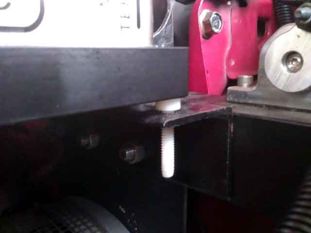
Posted: Sat Nov 15th, 2014 07:05 pm
The car is back together and charging. I double checked the settings in the web browser config page for the controller. I will bleed the coolant lines to remove any pockets of air in the morning and go for a drive.
Posted: Sun Nov 16th, 2014 01:49 pm
he short story, car runs great!
The
long story, I couldn't wait until morning so last night about 11pm I
took the car around the neighborhood. It was fine and I did a couple
laps going 10-15MPH. When I got to the driveway I opened the garage
door and proceeded to go inside. At this point on the driveway incline
the car started jerking forward and the tachometer gauge needle went
haywire. In the process of attempting to go forward I actually went
downhill. I ended up a couple houses down the street.
The
first thing I thought was maybe I didn't get the configuration right on
the controller settings. I went to get my laptop and hook it up to the
ethernet port on the Soliton1. I have gone through various computer
settings since the last time I connected to the controller and it did
not connect. Rather then pull up the documentation and configure the
TCP/IP stack on the computer with a specific IP and subnet I found
another way.
I have a game adapter/media
connector that is a standalone connection to my network. But this
requires a USB cable for 5.0v power. So the only thing I can think if
in a hurry is to use a laptop to power the adapter. So I put the laptop
under the hood with the adapter attached and then turn the ignition on
and run upstairs to connect through a web browser. Well no such luck.
The signal was to weak.
So off to the car
and I pushed it in front of my driveway. Taking a break every few feet
with a wheel chock quickly shoved under the rear tire as I gained a few
feet with every pass. I went back upstairs and connected without issue.
I double checked everything and it was correct. So I went back out to
the car and cycled the ignition. This time the tach worked and I was
able to get it into the garage. Today I drove it around and it would
cut out intermittently. So I turned around and got it into the garage.
Going on a hunch I thought what could cause an intermittent signal? A
loose wire, sure. But none was to be found. Then I thought, what does
the RPM sensor on the Warp9 motor require for a signal. Then I thought
hmm once in a blue moon the speedometer goes haywire. We are talking
maybe once in 3 months. Its a quick anomaly and I thought nothing of
it. Then it hits me, the vehicle speed sensor (VSS) and the RPM sensor
rely on being grounded. So for giggles I ran a short wire from the
transmission to the frame.
PROBLEM SOLVED! The car is great. WHY this problem just decided to exhibit itself now, I don't know. Keeping my fingers crossed.
Posted: Fri Nov 21st, 2014 09:53 pm
Well
the day after things started acting up again. I was able to make it
back to the house and finally tracked down the problem to a bad tach
sensor reading. I disabled the tach in the Soliton1 controller and have
been driving it for a hundred miles the past couple of days with no
problems.
Was this the problem the whole time? Maybe, but the cable re-routing and grounding was good measure and not time wasted. I will check things over this weekend and see if I can find any problems that would be causing a sensor reading issue.
Posted: Sun Nov 23rd, 2014 08:39 pm
Comical!
Yesterday I drove to my local gas station and talked to the people
working there. Not necessarily about the car, but I have developed a
few friendships there during the past years. After about 45 minutes
later I got in the car to go home. I heard the contactor engage but no
power. I happened to be in a very good place for this to happen so I
popped the hood and noticed the Soliton1 controller LEDs did not
illuminate. So off to check the fuses and all where OK. Then I grabbed
a test light and the positive to the controller was OK. Only one thing
left, the negative. I tested it and no connection. So I pulled the bolt
I used to ground the controller and filed some more paint off the metal
to make a better connection. All fixed and I drove home to make a more
through repair clean the metal grounding surface.
So
I drove it a couple times yesterday and today with no problems. Just on
a hunch I turned the tachometer sensor back on the Soliton1, and it
works!
So the problem this whole time could have been this ground wire for the controller.
Posted: Wed Nov 26th, 2014 07:37 am
I
am fully aware of the nature of the past few posts. It comes across as
the indecisiveness of a hormonal teenager. But car proBlems are coming
up all of a sudden that I have never seen before and the "fixes" I
think cure the situation are not working out.
Case
in point: I backed the car out of the garage 2 days ago and the tach
started jumping and the car started surging, again. So it was back into
the garage and I turned the tach sensor off in the Soliton1 controller.
I continued to use the car all day, no problems. So yesterday I took
the tach sensor off the motor and went to EVWEST to seek solutions.
They didn't bother testing it because I had come to the conclusion that
with the controller back fresh from being repaired it had to be the
problem. So Michael Breem from EVWEST removed the old sensor that had
been threadlocked in by them into the metal attachment ring that goes
onto the motor. He chased the threads, cleaned it and spun in a new
sensor. He charged me a very reasonable rate for the sensor and I was
on my way.
Well yesterday I installed the
sensor only to have the same problem return. So again I have turned off
the tach. I am going to try and diagnose this later on today.
I want to confirm with EVWEST that the power signal does not need to come from the controller to power the tach sensor for any reason. If that is the case I will hook the power to a known clean power line temporarily to see if that is the problem.
Posted: Thu Nov 27th, 2014 03:26 pm
Fixed! In my haste the ground wire I had made to ground the motor came disconnected (and the tach problem came back). So everything is grounded and I have about 75 trouble free miles on the car with everything working.
Posted: Sat Nov 29th, 2014 04:10 pm
All is well! With a couple hundred miles on the car I finished up the tach and ground wire routing. Everything looks nice and neat! It also dawned on me I needed to post a current engine bay picture.
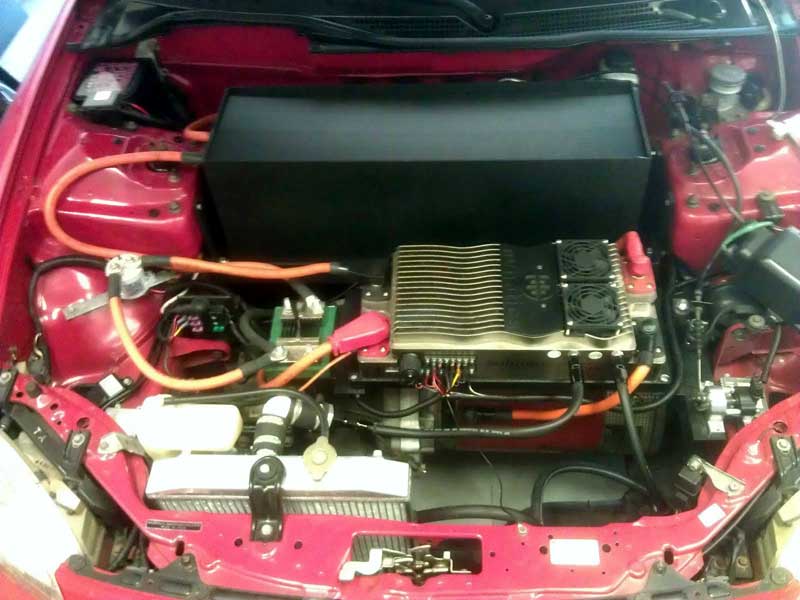
Posted: Sat Nov 29th, 2014 08:37 pm
I
began testing things to swap out the 30lb lead acid battery I have on
the trunk with a new 2.5lb lithium 12v battery I bought a while back.
I
turned the car on, disconnected the 12v lead acid battery and then
started loading the 12v bus with various items to see if the DC/DC
converter could handle the load. The converter supposedly has overload
protection so there was no real risk of damaging that.
I
turned the headlights on, radio, powered all the windows up and down
including the rear window which is known to take alot of power. I was
fully expecting that to "'trip" the converter and shut the car down. It
didn't however and everything was OK. To test things further I left the
ignition on while recharging with only the DC/DC converter powering the
12v bus. After about 30 minutes I put my hand on the DC/DC converter
and it was only slightly warm. I consider this a success.
I will work in the coming days to mount the new 12v battery underhood somewhere. For the time being I am leaving the 12v cable routed (but disconnected) to the trunk and the lead acid battery in place.
Posted: Mon Dec 1st, 2014 05:21 pm
I looked everywhere in the house for an old container I could
re-purpose for a battery box for the little battery, nothing!
What
I did manage to do is waste entirely to much time today with some, wait
for it.........angled aluminum! Wahooo I have found another thing to
make out of scrap!
I still have to drill holes, bolt it together, and then tear it back apart and prime/paint it. So it is a work in progress
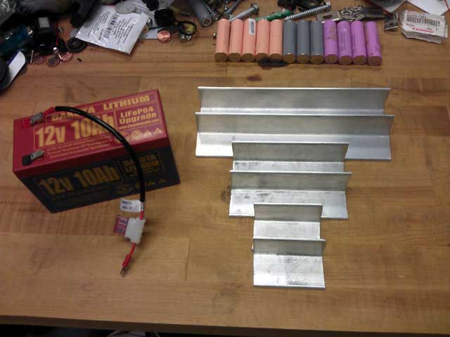
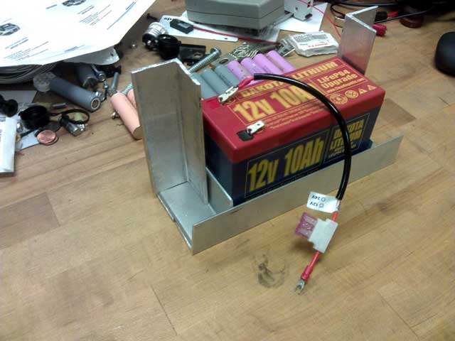
Posted: Sat Dec 6th, 2014 10:11 am
The
battery rack is all done. I need to buy a electrical diode from EVTV to
prevent the DC/DC converter from over charging this little battery.
Instead I am going to run a 1 amp fuse looped back over the diode to
the battery side to allow charging. That will be better illustrated at
a later date.
I did however determine that
removal of the front battery box is necessary to drill the holes
necessary to mount that battery rack. Any other method was deemed
unsatisfactory in that is was easily possible to mark-up the box from
either a hole drilled improperly or the drill bit "skating" on the
bedliner surface and moving the drill bit position. Also there is
little room inside the box to drill outward for the holes and NO way to
drill from the firewall side into the box. Doing this ensures this will
be done right the first time.
As far as assembly of the battery rack went, it was trial and error with stainless steel bolts I thought where strong enough and looked good. The thing is that when I started tightening the bolts into the nylon locknut's the heat it generated snappen the bolts. So I did what I should have done in the first place and bought slightly thinker Grade8 bolts to go into the locknuts.
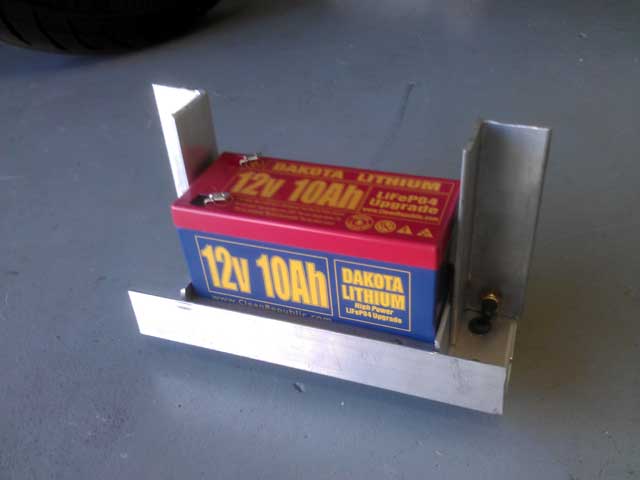

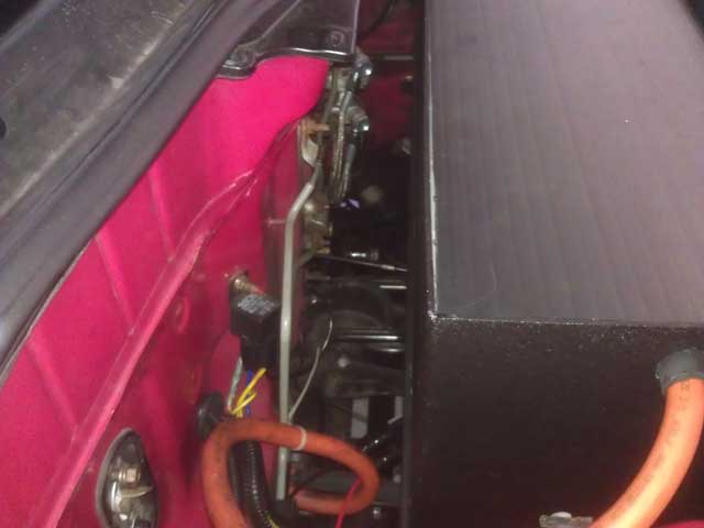
Posted: Tue Dec 9th, 2014 03:38 pm
I diode was ordered and the battery was mounted. It all went trouble free!
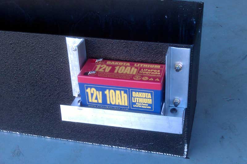
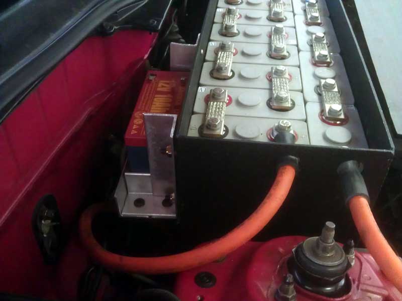
The
bolts on the right side go THROUGH the battery box in the extra room I
had in the box due to my battery arrangement. On the left side the bolt
head to up against the battery box. Taking up the extra space from the
bolt head I used a couple washers on the top bolt. That bolt was a very
small stainless bolt that I was originally going to use for the battery
mount. This bolt does not carry any real load and is just there for
looks as much as anything.
I left the extra
metal on the battery mount in case I need to use it to mount the diode
or anything else I can think of. Otherwise at a later date I will cut
the top of the mount at a 45degree angle going towards the rear of the
car.
The battery is grounded to the frame right at the firewall. The positive wire will go through the diode and then into the fuse junction block next to the controller with a 5A fuse. I might go up on that based on accessory load. Then the diode will have that 1A fuse letting that current back into the battery to charge it.
Posted: Fri Dec 12th, 2014 09:59 am
The
diode is due today or tomorrow. It's raining for the next 10hrs on the
West Coast which is much needed so a perfect time to work in the
garage.
I wanted to touch on something that was brought up yesterday at a local STARBUCKS.
I make a habit of frequenting my local STARBUCKS once a week. Usually in the morning. If I go in the Del Sol I try and get a spot up front and "pop the hood" for people to admire. It's an interesting crowd of people. Most with enough money to buy a Tesla, to be honest. Yesterday while getting coffee I was talking to someone about the car and someone who had just got their coffee was on the way out and mentioned briefly in passing that "I must be upset at the price of gas going down". I smiled and everyone went on their way.
On the way home I got to thinking about it. And yes, I am upset at the price of gas going down, but not why you think. I am upset because back when I was born (in the 70's) I heard of this happening once before. Even my parents have memories of stations rationing gas that would alternate on license plates that ended with odd or even numbers. But them came the 80's and the 90's and while emissions where looked at with the inclusion of catalytic converters and SMOG pumps, etc not allot was done on increasing the mileage of these vehicles. And people went back to owning big vehicles that fell under commercial vehicle status that made them exempt from certain emission requirements. The car industry got lazy and Ford and GM where "cleaning up" with sales of the F150/Escalade/Hummer.
Fast forward to present day. Most trucks are no longer exempt from what they used to be. But Americans are forgetful and we like big things. Big cars, big meals, big women, big everything! So we don't like being "told" to conserve.
Converting the Del Sol to electric was never about saving money. In fact putting $17,000.00 into a $3,000.00 car was never about economic sense. A quick table napkin math estimation is enough to disprove that.
So whats it all about? Well its about changing peoples misconceptions about what a electric car is and what it can be. I common term that gets thrown around is the reference to a golf cart. I don't take offense to that because most of the time that is their only point of reference. They have not driven an electric car and after talking to them most of them have not even been in a moving electric car!
I must admit I don't just give anyone a ride in the Del Sol. But if you have talked to me for a while, don't ask, I have time and have genuine interest in the technology/car, I will take you around the block. And I never let them drive the car. Everyone who has ridden in the car has their own mindset changed. And changed in such a way that its not easily kept to themselves, and that's exactly what needs to happen. I am not just giving one person a test drive but often time its the 3-4 other people this person relays to that is sight unseen.
If you can afford is buy that Nissan Leaf, Ford Focus EV or Tesla Model S. Or if you have a car you love already because of family ties or a personal bond, convert it to electric! My own reasons are because I am an independent person and I like doing everything myself, almost to a fault. I didn't approve of not knowing how to work on things myself.
So I guess what I am saying is do your EV promotion from the drivers seat if possible! I really hope Americans can show the world that we are smarter then falling back to old habits and buying cars outside of their practicality. Even today I heard reports sales of large SUV and Trucks where on the rise and mostly being attributed to falling gas prices. Then exception to this may be customers looking to make one last 2014 purchase to "write off" on taxes for this year.
OK, I am done, never trust me with double-shot of espresso again!
Posted: Fri Dec 12th, 2014 11:04 pm
The diode did arrive today. I have a e-mail to Jack Richard to verify the direction of flow, I didn't see any markings.
I uploaded almost every photo of the conversion to a new gallery. I also removed any watermarks. These photos are of a higher resolution then before.
http://www.techvelocity.com/delsolgrouped/
Posted: Sat Dec 13th, 2014 09:15 pm
The diode bracket is made/installed and everything is wired. One problem however. I ran out of 1amp BUSSMAN blade style ATM fuses. That is the size fuse I am going to try charging the 12v battery at.
I had things to order anyhow on Amazon so I added those to the kitty bag of goodies. But that means waiting a few days for the order to arrive.
Posted: Sun Dec 14th, 2014 04:29 pm
My Amazon.com order arrived today, on a Sunday, from the U.S. Postal service! I was not expecting this, big UPS!
In short order I disconnected the lead acid 12v battery but just covered the connection over in case I have to hook it back up in hurry on the side of the road! I then connected the little 12v battery and turned my JLD404 meter on for a 25% charge from today's travels around town. I will see what the 12v battery reads after the recharge and then again after a short trip I am going to take tonight. Then as the week progresses and everything is "OK" I will pursue removing the big 12v battery altogether.
Posted: Mon Dec 15th, 2014 12:57 pm
My thoughts from 3 days ago look to be correct regarding the American public: http://cleantechnica.com/2014/12/15/elio-motors-another-solution-greener-transport/
Taken from the article
"Consider some of the sales gains for several large vehicles in October:
Lincoln Navigator sales were up by 38%
GMC Sierra sales jumped 12.5%
Ram pickup sales were up 33%
Meanwhile, the Ford C-Max Hybrid saw sales fall by 22.5%, while the Toyota Prius fell by 13.5% in October. Clearly, these are stats that should be troubling to the clean vehicle movement."
On the subject of the Del Sol I felt I had enough miles accumulated to justify removal the lead acid battery, so I did.
Posted: Thu Dec 18th, 2014 08:23 pm
No news is good news. I am putting about 50 miles a day on the car with no issues. It's a mixture of day and night driving. The 12v lead battery is now removed from the trunk. And this weekend if I find time I may remove the 12v cable that leads from under the hood to the trunk.
I took a black permanent marker to the top of the bare aluminum angle metal that I made the battery bracket out of. This way it is less noticeable. Long term is cutting the brackets like I spoke of before.
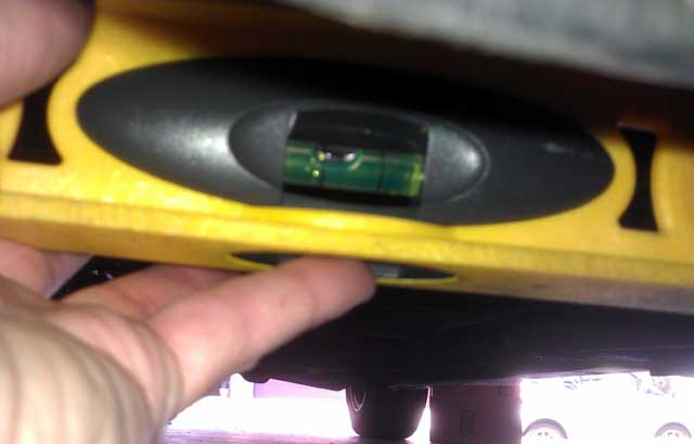
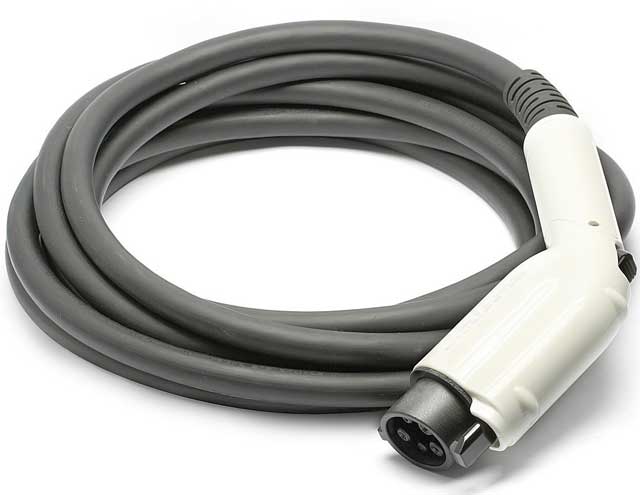
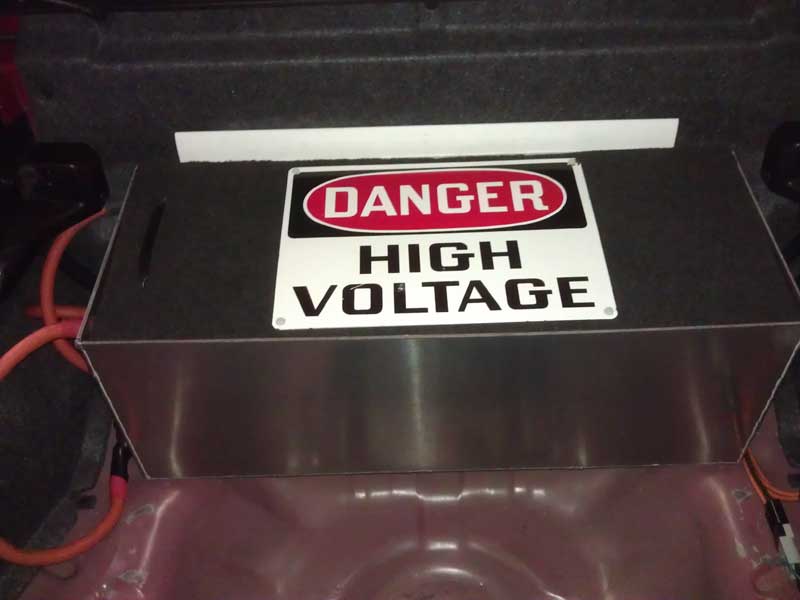
I am still working on the bottom trunk carpet. I have to reinforce the piece of fiberboard to make it more rigid.
Posted: Wed Jan 21st, 2015 01:53 pm
How I spend my time.....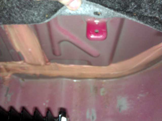
Here is the OEM Honda rear trunk support hole for the piece of fiberboard.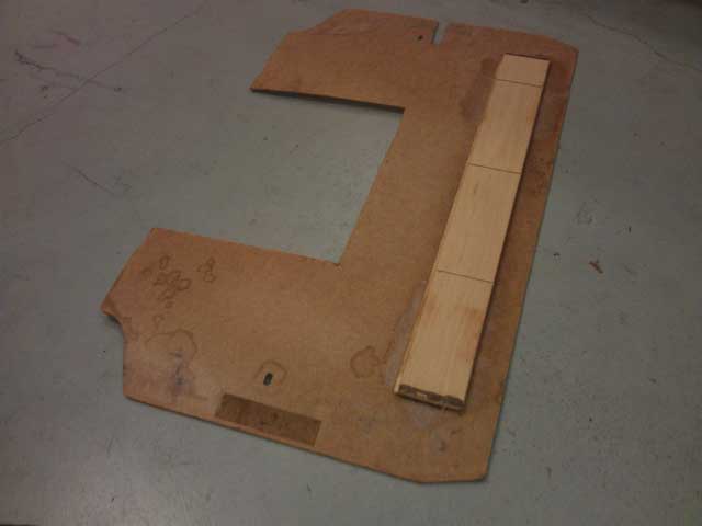
Here is a piece of wood flooring I used to reinforce the board.
Here is the board edges ground down to form a bevel so it sits more securely.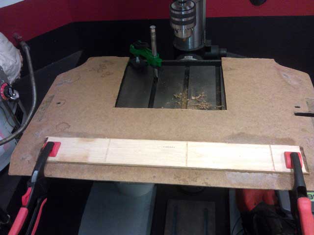
Flooring glued and clamped into place.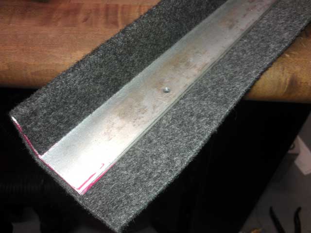
A
piece of angle aluminum I drilled and tapped for threads before glueing
carpet to. This will be to form a ledge in the trunk for the board to
rest on, alternatively I can drill and use plastic push rivits to
secure it.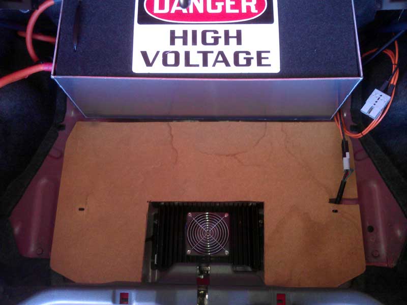
The board test fitted into place before carpeting.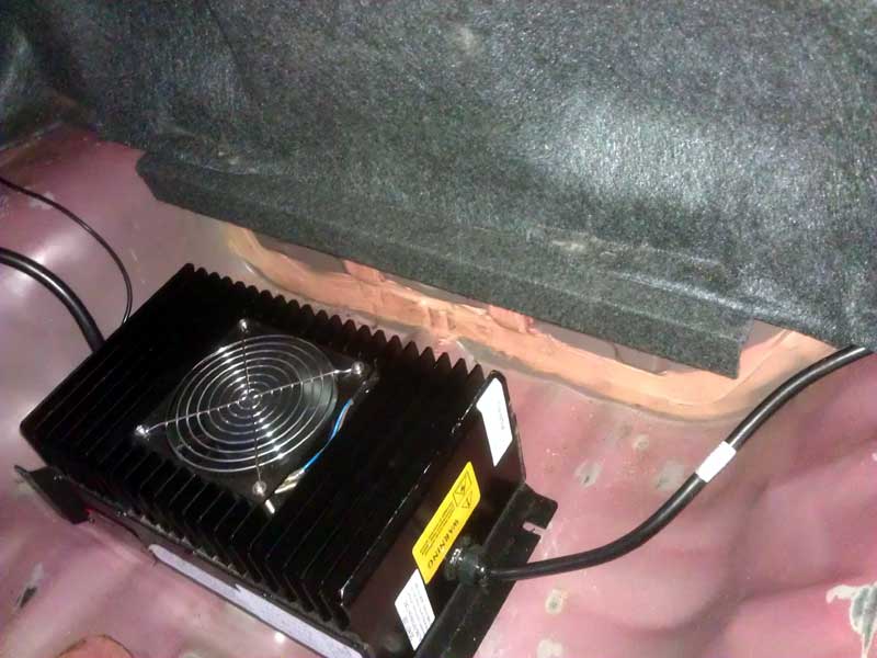
The piece of carpeted aluminum mounted in place to form a support ledge.
No idea why this excites me so much, but I finished the 110v charge chord.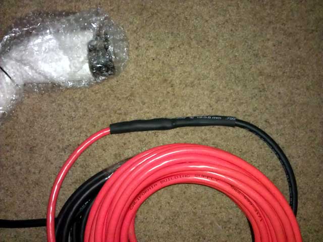
It
add's 10lbs to the car however its 75ft of cable. I bypassed the J1772
simulator module, the plug is always hot and doesn't need to signal an
EVSE to turn on.. Plugging a hot J1772 plug with 110v is not a concern.
The charger itself has a slow engagement so its not going to arc when
its connected.
I
have the car charging on a 50% drain with the 110v cord. My way of
stress testing it I suppose. It will be about a 7 hour
recharge.
The
rear trunk floor is almost complete. I added corrugated plastic with
the flutes going longways (stronger then going sideways) to add
lightweight support.
Posted: Sat Jan 24th, 2015 04:31 pm
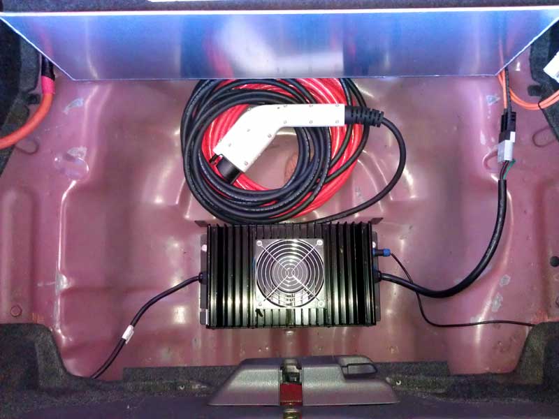
Charge
cord placement in the car is perfect. It doesn't get in the way of the
chargers airflow to cool it. Of course this is because the cord is all
neat and tidy. If I ever have to use it I hope it can be rewound up the
same.
The
recharge cycle went without a hitch last night. The cable at join
splice between the extension cord and the J1772 plug was the same
temperature as the cord. So that tells me its a good connection. As
expected the warmest part of the cable was where it enters the A/C
receptacle on the wall. But even then was are not talking warmer then
80F.
220v charges the pack @ 11a (2500watt)
110v charges the pack @ 6a (1400 watt)
The car gets ROUGHLY 1a of use per mile of travel.
I hope to get the trunk carpet done tomorrow.
Posted: Mon Jan 26th, 2015 03:00 pm
99% done?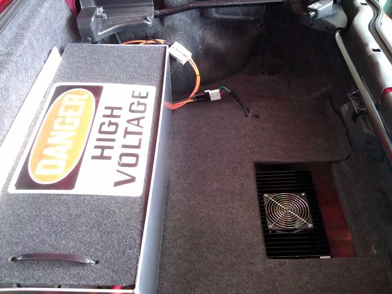
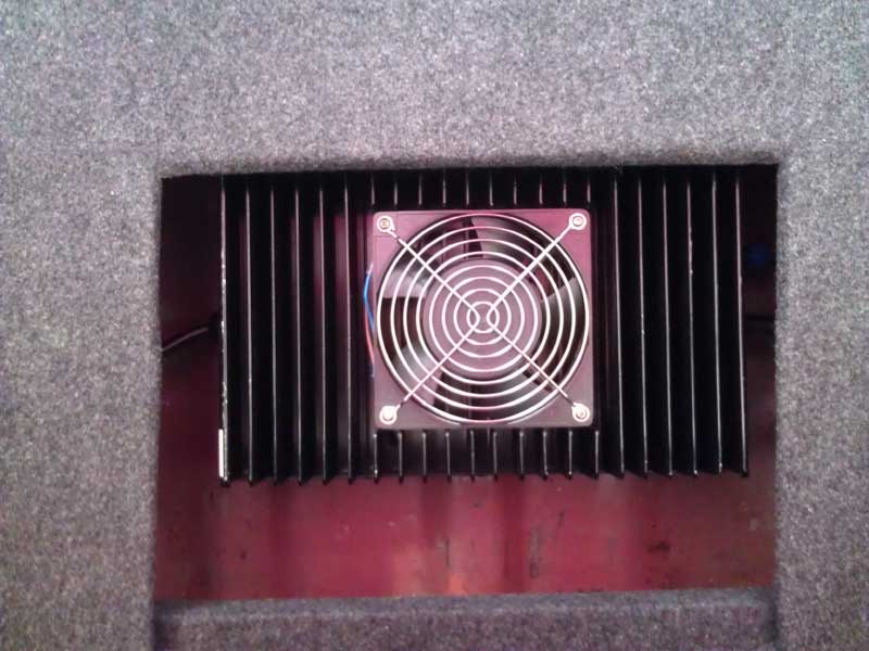
There
is about 1" of excess carpet towards the back. Rather then just cut in
I am going to fold it under and glue it on the back. This way there is
no lip that could fray.
Still debating on wire mesh to cover the opening above the charger.
Happy with it so far!
Posted: Fri Jan 30th, 2015 02:48 am
And
for the of you who are curious, here is the level of OCD I put forth on
the trunk panel. This is a view from underneath. Piece of wood floor up
top. Corrugated black plastic below that and carpet folded back
underneath. All glued and allowed to set for 24hrs secured with clamps
between the different segments. 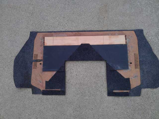
Posted: Fri Jan 30th, 2015 11:03 pm
OK lets play "catch up".
Yesterday
the car died, in the exact same location it did last time. Going up a
slight incline under half load. I was able to get it into a shopping
center. Then I went and got my computer which still for whatever reason
doesn't want to connect to the Soliton1 directly, despite entering the
right IP, subnet, etc. I went and rented a tow dolly only to come back
and find the angle was to sharp to load it safely without scratching
the airdam. It was returned and the UHAUL store was nice enough to
reverse the charges, so nothing lost there!
I
left it in the shopping center overnight. It wasn't in the best
position for towing it with a tow strap behind a truck, which was my
idea. So about 1am this morning with the parking lot cleared I made the
goal of getting it across the parking lot. maybe 200ft to a better
location for loading. Slowly I did manage to do that.
This
morning my Dad drove his Avalanche and we hooked it up to a 12,000lb
tow strap. Mind you, I bought this strap 10+ years ago and it went
unused. I just thought it was a good thing to have, and that proved
correct. So he drove the truck with my steering the Del Sol.
Remembering to take wide turns and brake slowly. We got the car to my
neighborhood which was at a slight incline. Then with him pushing I was
able to make a run for the driveway. Success the car made it into the
driveway but not into the garage.
Later
on in the day I got my Moms Touareg and some moving blankets. I padded
the front end of the VW and slowly brought it up against the Del Sol. I
then got into the Del Sol and my Dad pushed the Del Sol with the
Touareg while I piloted the Del Sol.
I then got the wireless network adapter that was known to work on the car and hooked it up.
Under the web interface I was able to read the error codes which was:
ErrorRun timePrecharge timeout, no voltage [0x00, 0x0000]0m 1.150sPrecharge timeout, no voltage [0x00, 0x0000]0m 1.130s
I
checked everything and the controller was getting 194v at the
controller terminals. So it has to return to EVNETICS for repair.
Digging deeper I found the copper lead wires coming from the brushes of
the Netgain Warp9 motor to simply PULL OUT of the brushes when I was
trying to pull the brushes for inspection. I was able to view a portion
of the commutator and it doesn't look pretty. So I am pulling the motor
to. I will revise this post later, its just been a long day and I am
tired.
Some
thoughts right off the bat, I blame myself for not checking the
condition of the brushes sooner. That was probably the problem that
shorted the Soliton1 the first time. I also should have opted to cool
the brushes with forced air as I think heat attributed to the problem.
Posted: Mon Feb 2nd, 2015 05:30 pm
Picture overload here!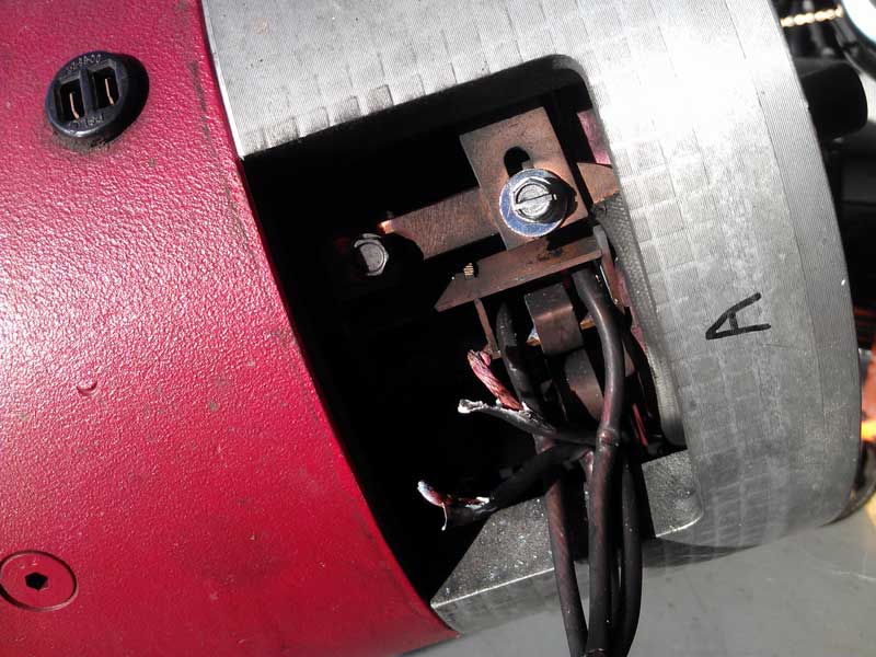
The wires pulled out of the brushes.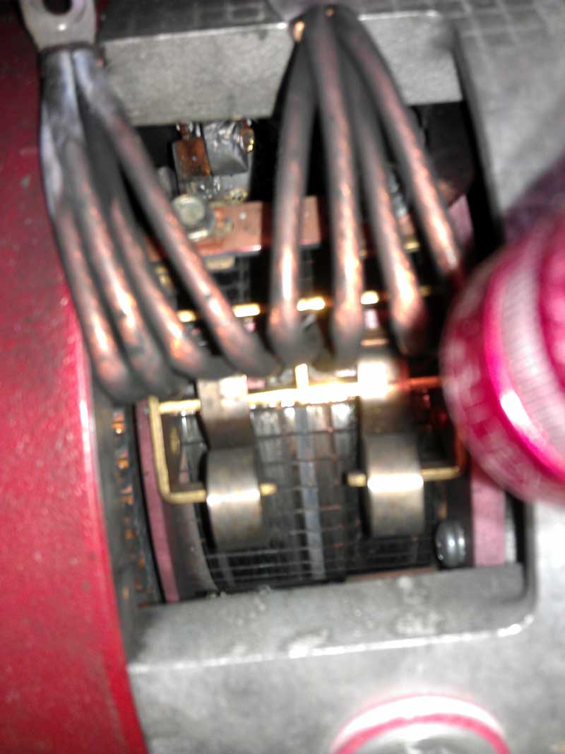
View of the commutator.
The magical Unicorn dust that come out of the motor.
I
have inquires out on repair. Even though I did buy the motor from them,
I think this is beyond what EVWEST can do in-house and then at that
point why would *I* send it out to the eventual place it needs to go
for repair? I can, and I will.
Posted: Mon Feb 23rd, 2015 12:49 pm
After
going round and round what what seemed likes weeks, the man who wanted
to sell the AC50 motor/controller combo no longer wants to. I was just
happy to get ANY response from him at this point.
Hmmmmm, what to do.....
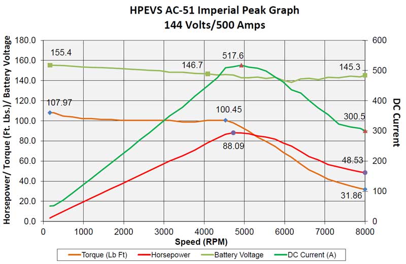
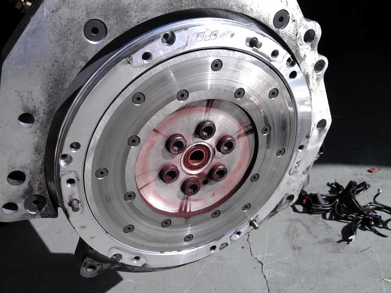
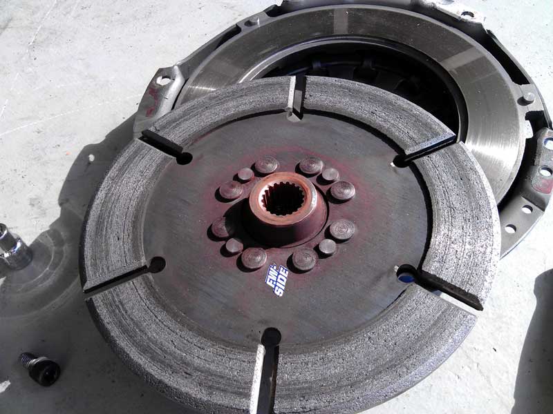
I am picking up the motor and controller from HPEVS in Ontario, Ca tomorrow!
Posted: Fri Apr 17th, 2015 12:47 pm
Everything is in the garage! I may try and mount up the motor mount plate to know if I need to shim up the flywheel collar. I know I need a controller mount and cables from EVWEST so that will be a trip for next week.
Posted: Mon Apr 20th, 2015 09:44 pm
I
am off to EVWEST tomorrow to get various motor cables and the
controller mount. I am taking the old motor, the new motor the
flywheel, etc. The fastest way to get the car back on the road is to
get everything matched up and done at once. I will likely need to space
the collar for the flywheel more then it is now.
An interesting sight is the fact that I have all these parts in the back of the smart car for the trip!
Posted: Tue Apr 21st, 2015 09:21 pm
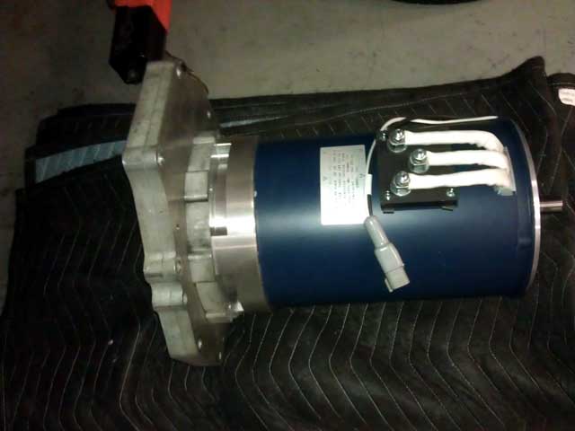
EVWEST
went out of their way to get me back up and running. The motor coupler
gave some issue going on the new motor. But after literally 20 minutes
with a heat gun on the coupler, Michael Breem hammered it on with a
block of wood. And it was within spec! You only really get one try
before the heat from the metal transfes to the motor shaft and its not
going anywhere except back off.
While
at EVWEST I heard of a couple things that are going to take the EV
world by storm. But I dare not repeat my last slip up with EVTV and
EVWEST who currently seem to have a war of the words happening, not
going to take sides.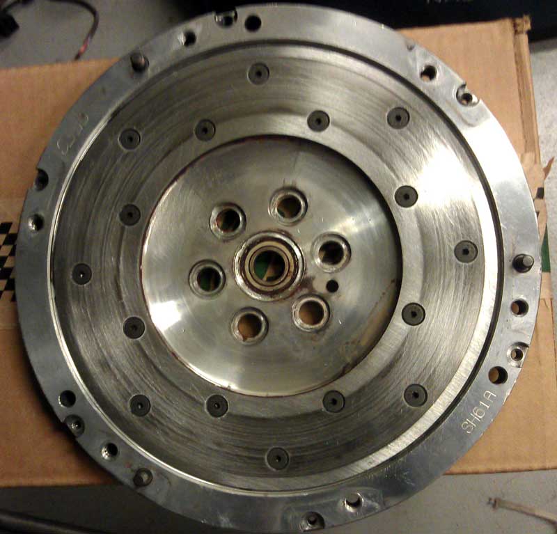
One
thing I noticed today is the bearing on the flywheel grinds a little
bit. I think what happened it when I went to heat up the flywheel bolts
to remove them, the heat transferred to the bearing and it cooked it.
I am also playing around with the mounting plate and trying different positions with the motor clocked different ways.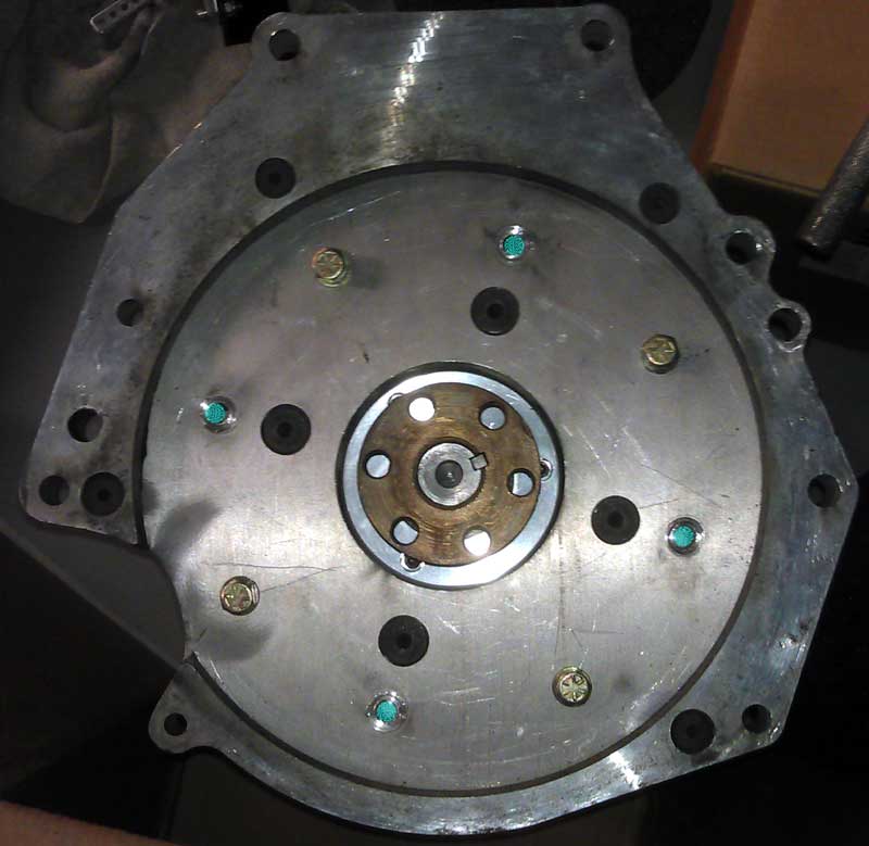
EVWEST
was smart when they made my adapter plate and made multiple holes that
the motor could be mounted on. In the picture the green dots indicate
where the Warp9 mounted, and the new bolts are installed.
So
I bought a set of cables and a mount today until I know what else I
need. I spent pretty much the day at EVWEST so sleep is essential right
now!
Posted: Wed Apr 22nd, 2015 10:17 pm
A new flywheel pilot bearing is coming and I await that before going any further with re-creating mounts\wiring\etc. It really doesn't make sense to do anything until I can bolt the motor to the transmission.
Posted: Tue Apr 28th, 2015 01:42 pm
Well,
come to find out the bearing was never sent as I just got a "quote" on
shipping sent to me that I that I had asked for a while back. I had
just figured he sent it but I guess not.
One
thing I was able to confirm is the hole in the flywheel is a straight
bore. So pressing the old bearing out and installing a new one will be
easier.
And I am busy these next 2 weeks so not much is going to happen on the car.
Just some pictures for your perusal.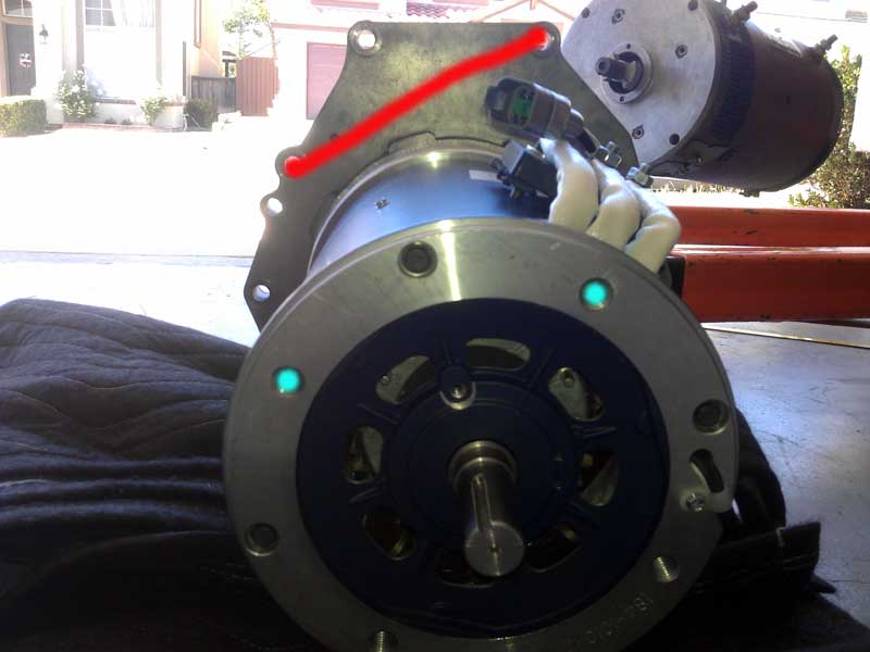
The
controller mount choice I have come up with is mounting the controller
at a angle. It's not my first choice but it does have the only added
benefit I can come up with is the ability to easily bleed air out of
the controller chill plate. I have time so a better solution may
present itself. Either way I have to cut 1.9" off the plate so it will
clear the motor plate end. And then at that point I will come up with a
mount to secure that end consisting of about 10" of angle aluminum!
YES! I get to fabricate something! It's become a favorite pastime of
mine.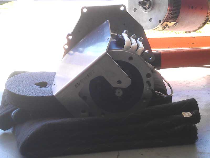
This is just a "mock up" but generally represents what I am trying to accomplish.
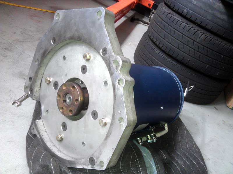
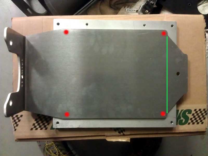
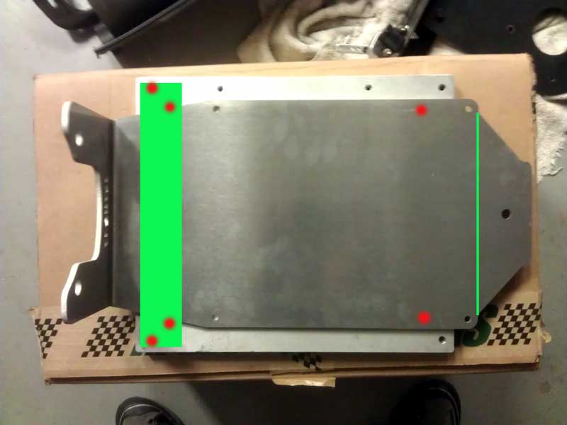
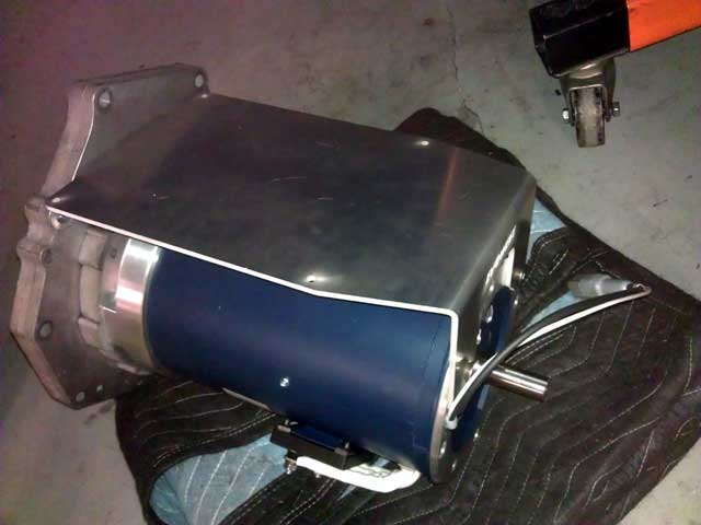
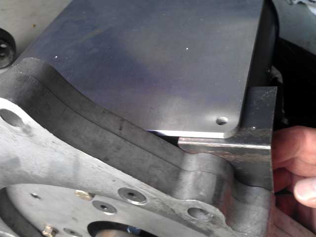
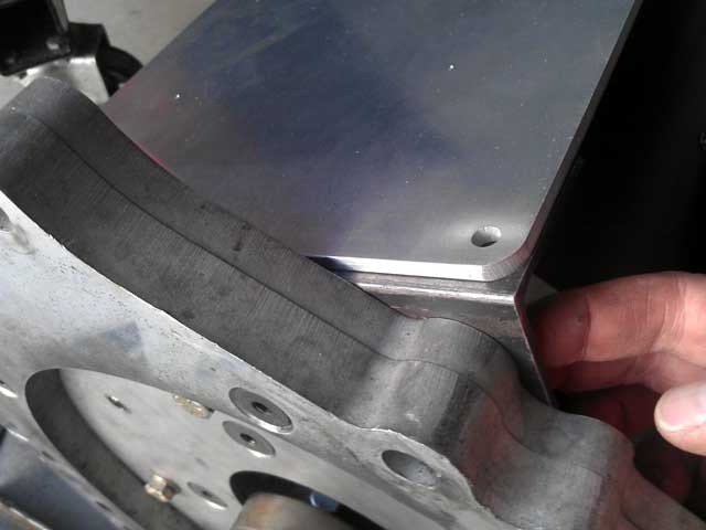
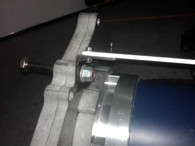

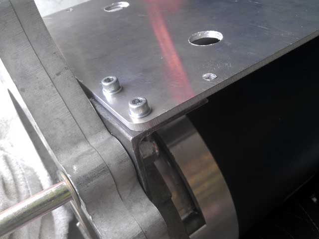
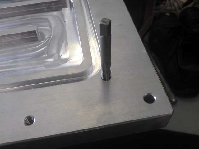
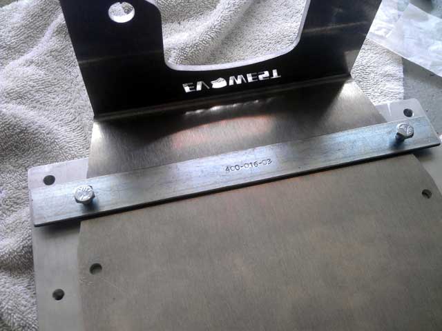
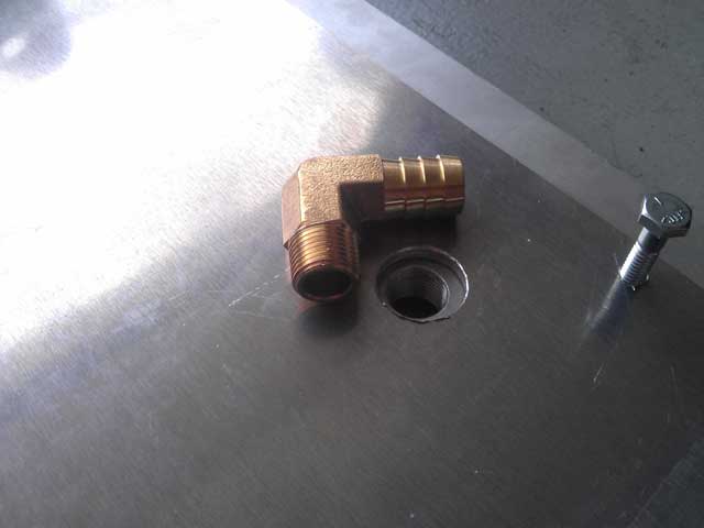
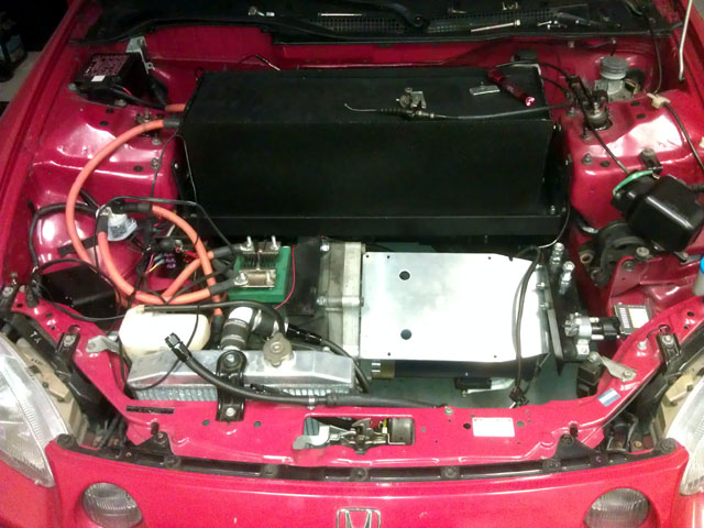
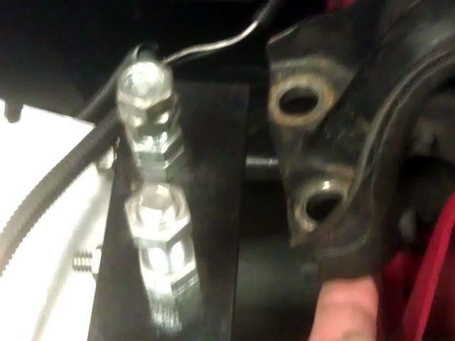
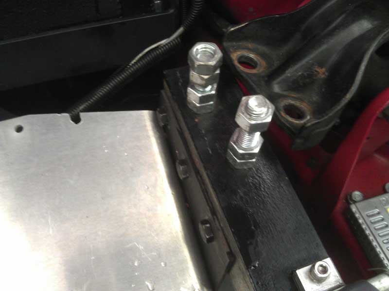
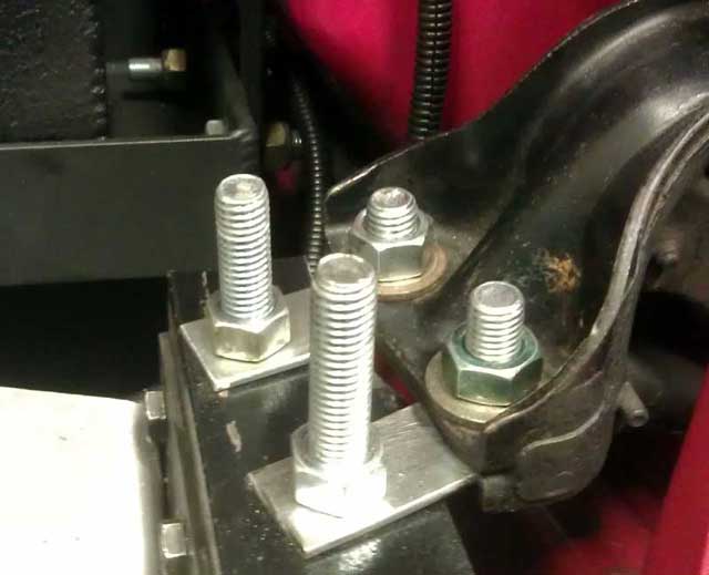
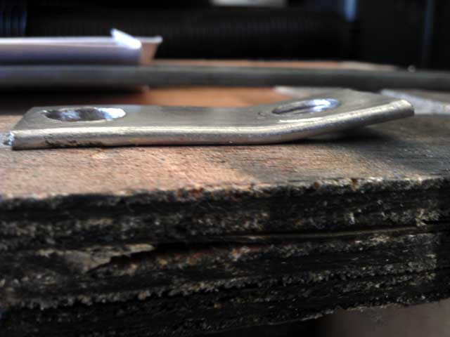

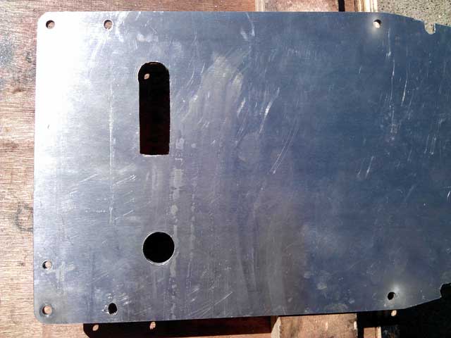
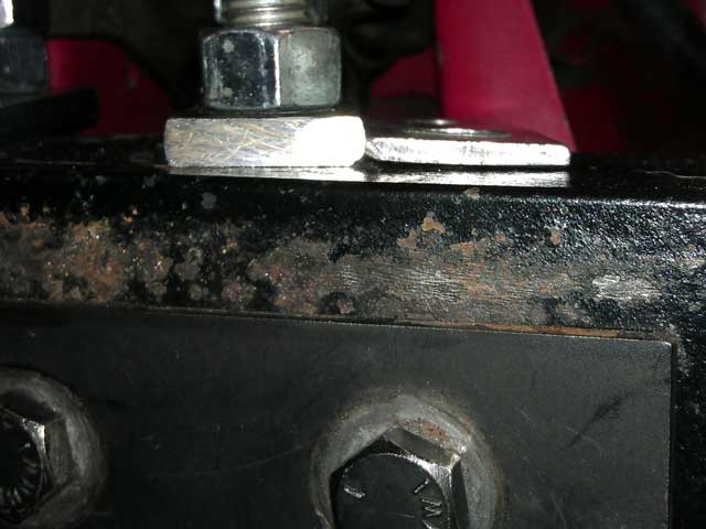
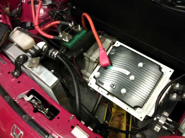
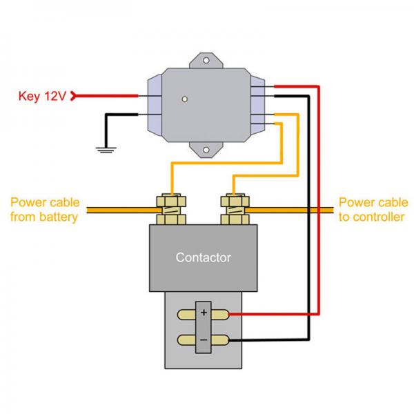
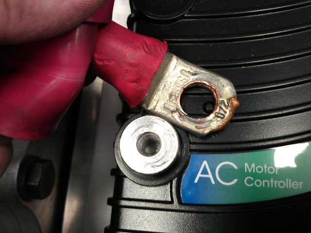
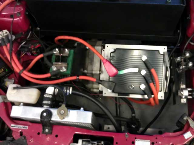
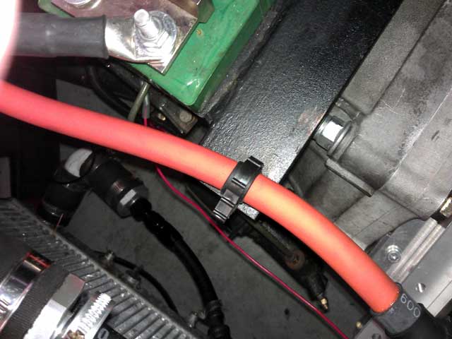
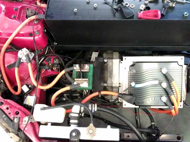
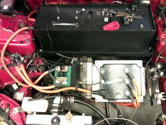
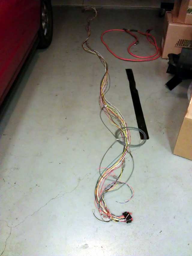
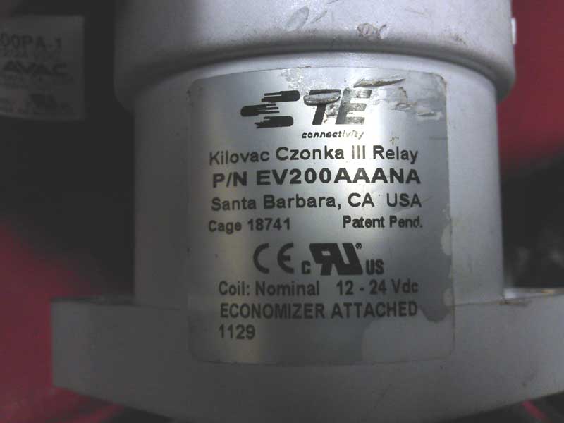

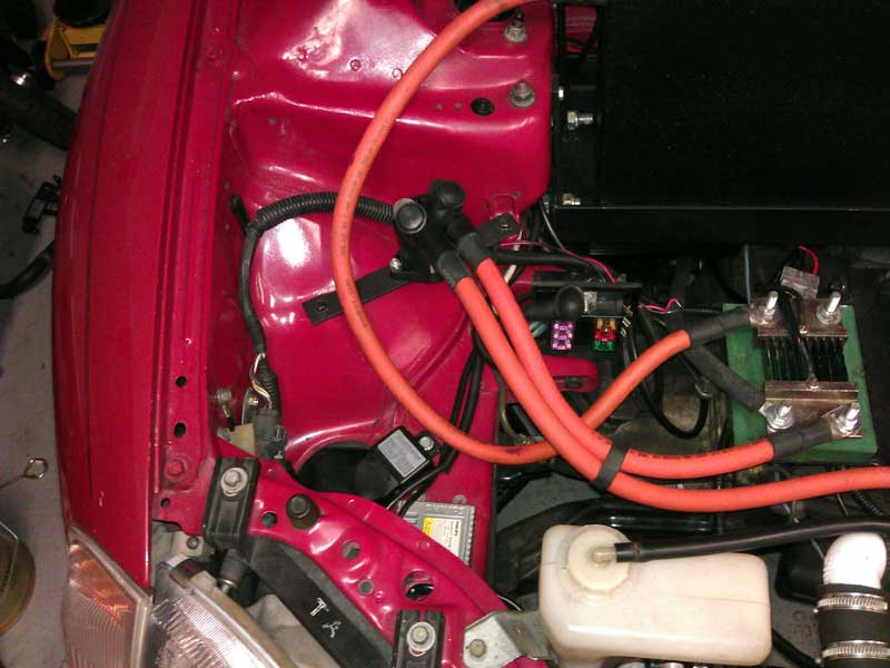
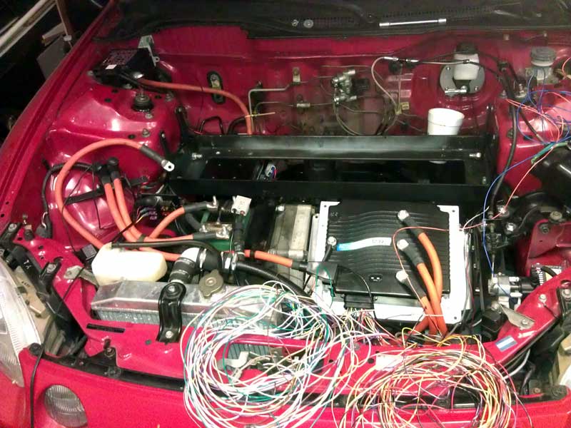
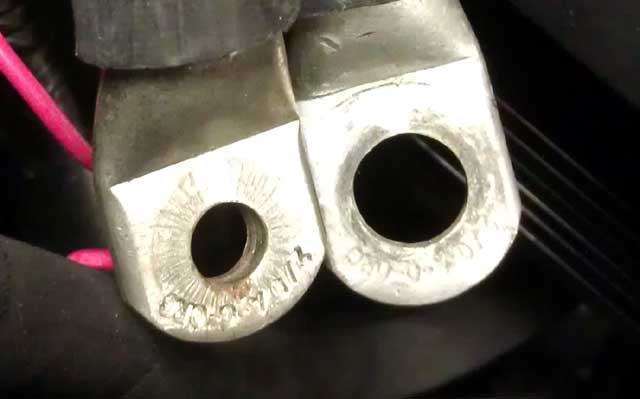
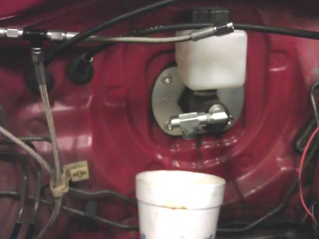
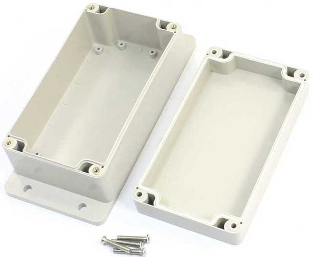

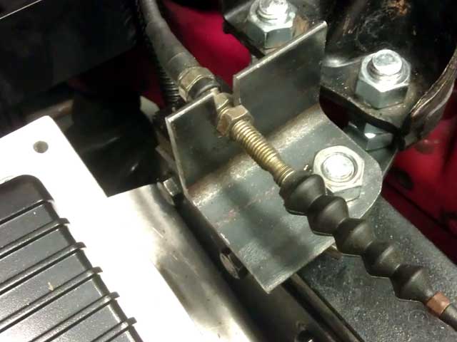
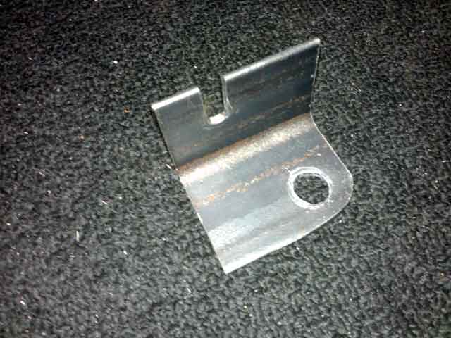
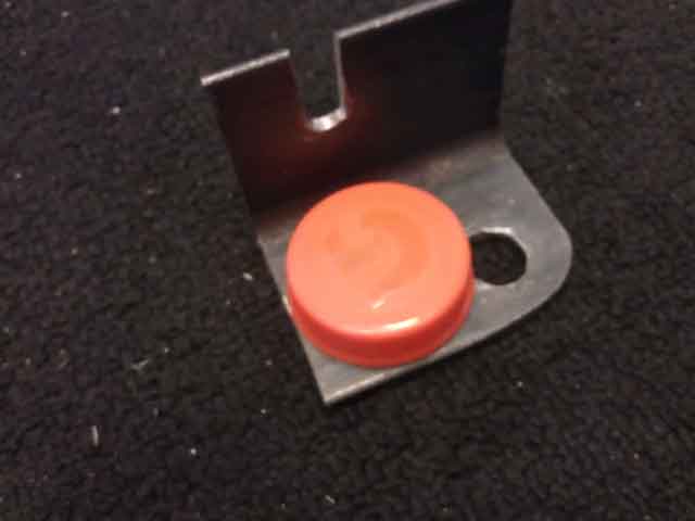
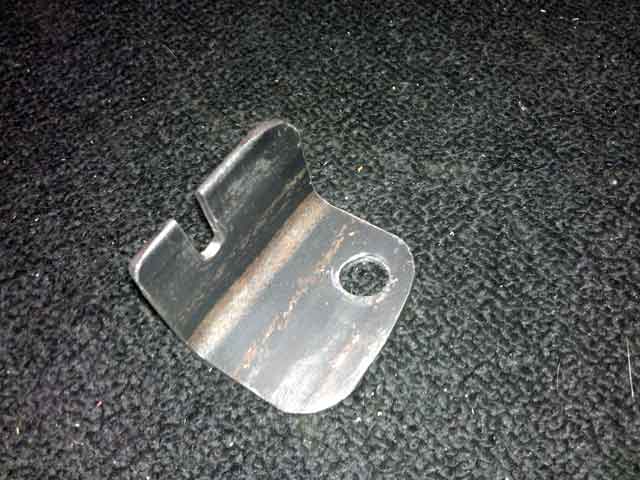
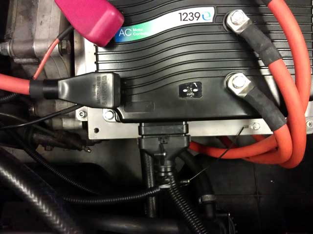
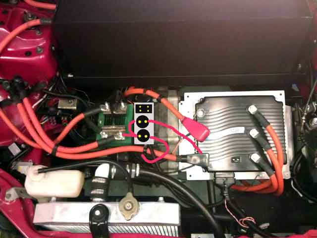
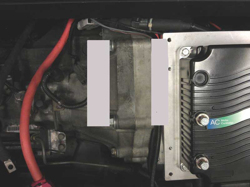
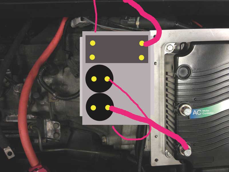
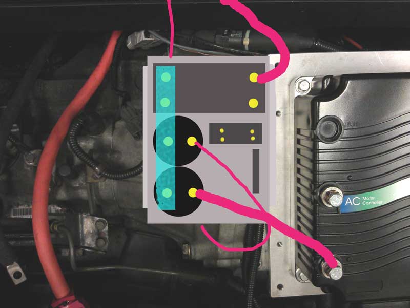
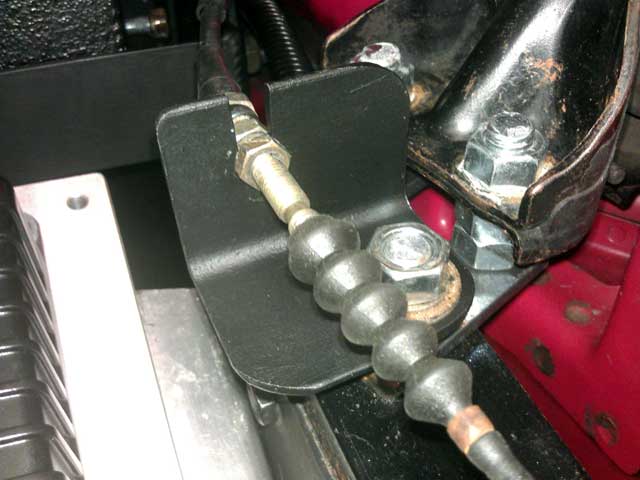
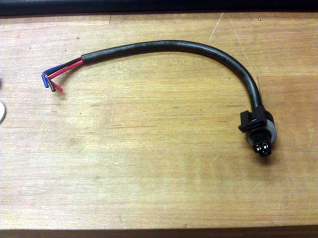
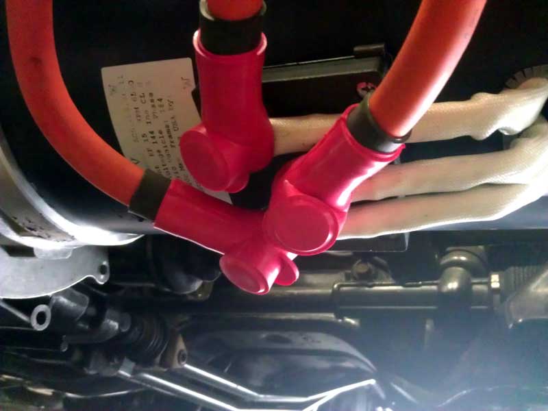
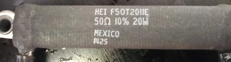
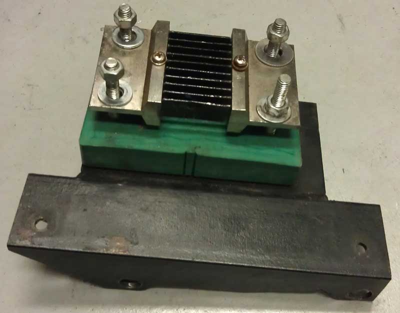
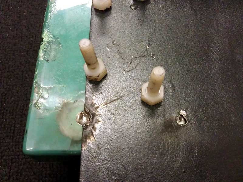
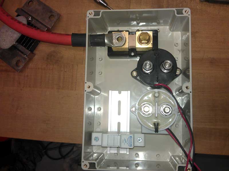
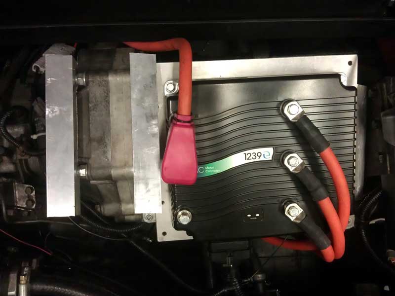

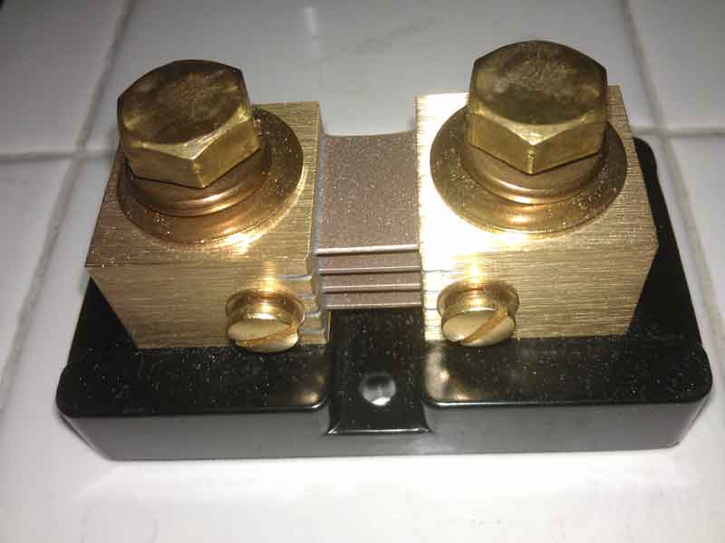
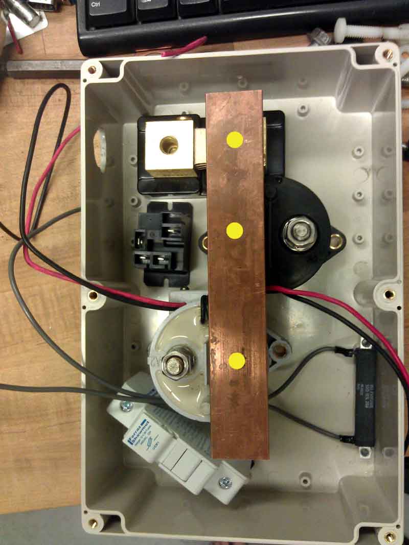
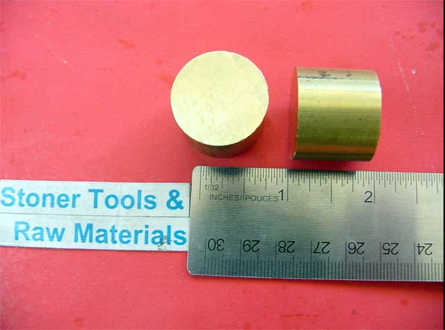
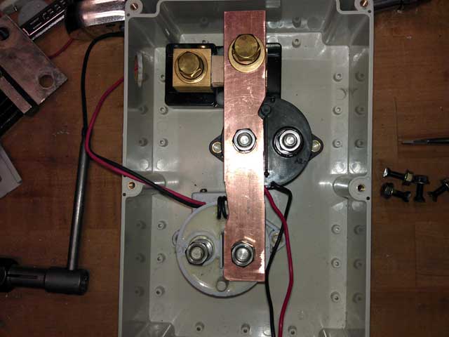
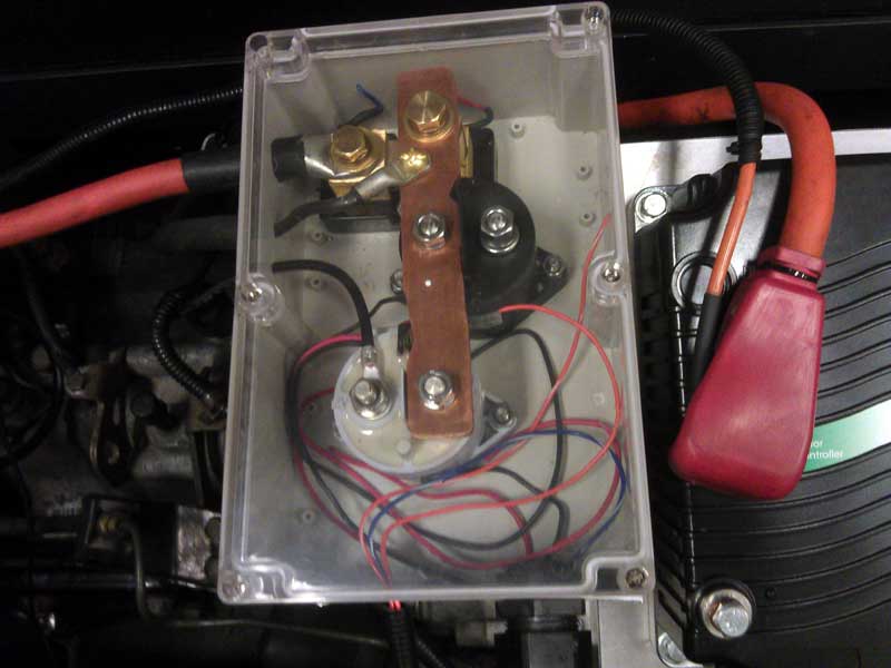
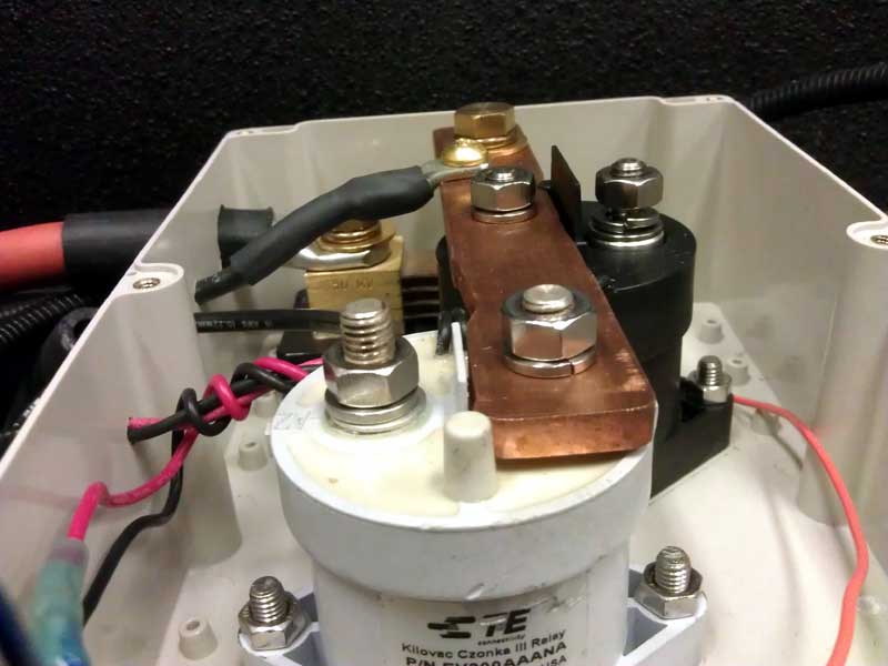
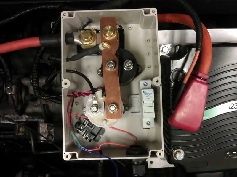
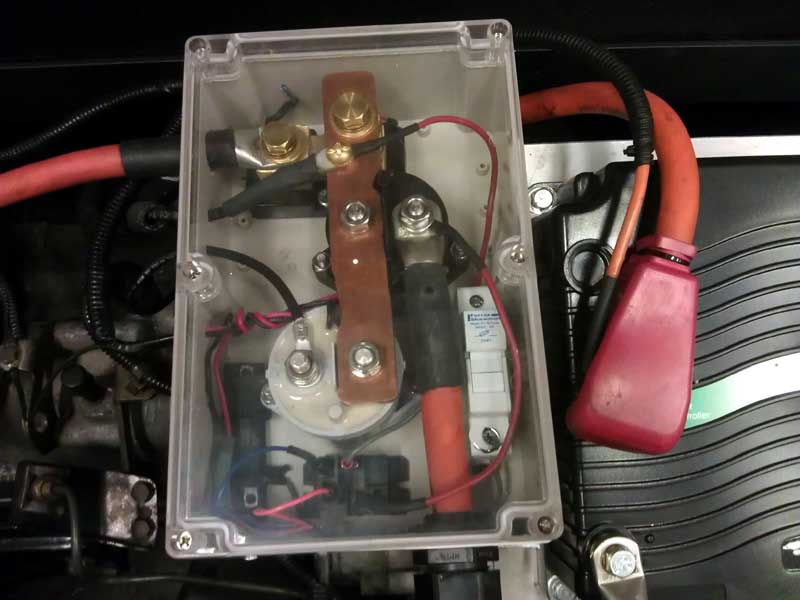


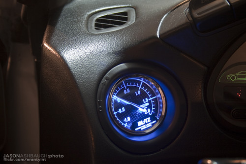
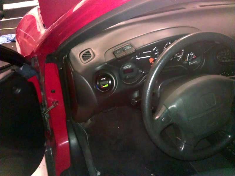
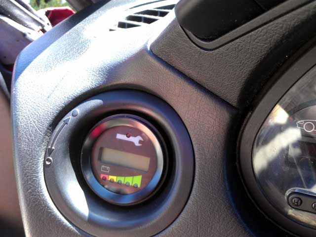
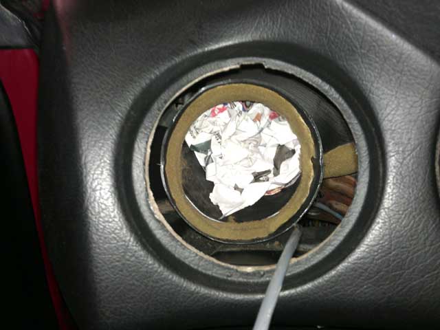
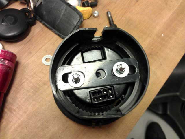
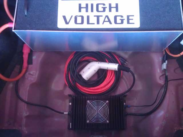
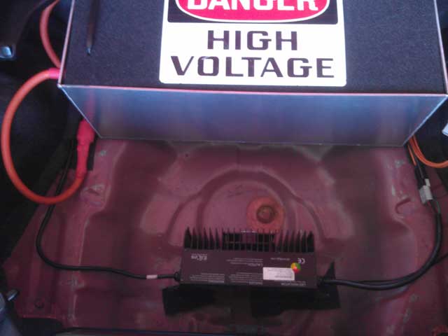
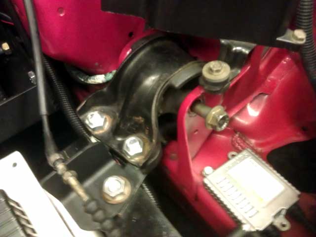
© TechVelocity